0 Preface
In recent years, in the multi-screen integration of high-definition TV, living room entertainment center and other application scenarios, iPad, smart TV, OTT set-top box, etc. are more and more accepted by consumers, although its business forms are constantly changing and developing. The user's final access method is biased towards the use of wireless technology. Generally, the most common wireless home access technology uses WiFi, namely IEEE802.11n, such as Gehuafei, Xiaomi Box, and LeTV. The latest Apple MacBook Air uses a more advanced IEEE 802.11ac to achieve a throughput of more than 1 Gbps, and the access point Airport TIme Capsule uses beamforming technology to represent the next generation of wireless communications represented by Apple. The schemes all point to the multi-input and multi-antenna technology [1]. In the next-generation mobile communication technology LTE, multi-antenna MIMO technology has been clarified as its mandatory option. Incidentally, in the radio and television wireless coverage, due to the high transmission rate required by high-definition video formats such as high definition and 4K, In the next generation of terrestrial digital TV broadcasting standards, MIMO is also listed as an important technical solution.
By using techniques such as space-time coding, MIMO utilizes the non-correlation in the propagation channel to multiply the channel capacity of the communication system, that is, the throughput, without additionally consuming the spectrum and time domain resources. In a conventional single-antenna communication system, especially in a mobile communication system, multipath in a channel is considered to affect communication quality and needs to be processed by a special technique, but in a MIMO system, these non-correlated sub-paths are used. Then, with the help of mathematical algorithms, the performance of the whole system can be improved. In other words, MIMO technology utilizes the spatial, temporal, and frequency domains in the propagation environment to push high-speed wireless communication to a new level. Since the algorithm of MIMO terminal relies on the channel environment, that is, intelligently optimizes the performance of the communication system according to the channel environment, this makes the channel model an important reference for its theoretical research and implementation.
As a result, the final MIMO terminal performance test and evaluation, whether in the development phase or the certification phase, strongly relies on the channel model. Traditional wireless terminals typically use the OTA (Over-The-Air) for final performance evaluation. The OTA uses a anechoic chamber to create a non-reflective free space to evaluate the RF and antenna overall performance of the wireless terminal; As mentioned above, in order to evaluate the multi-antenna terminal, the so-called MIMOOTA technology must real-time reproduce the channel model in the laboratory, making the MIMO terminal test truly repeatable and controllable due to the technology. The implementation involves the theory of radio wave propagation, channel modeling, digital signal processing, optimization algorithms, electromagnetic fields and microwaves, which greatly deepens its complexity and professionalism.
The Broadcasting and Television Planning Institute has been involved in the research of multi-antenna test methods since 2011. With the assistance of HWATECH, it participated in the international comparison test from 2012 to 2013 using the built-in single-cluster method environment, because this test system is from software to The ideas and theories of hardware are all proposed and implemented by ourselves [39][40]. Therefore, for the exploration of the principle and practice of multi-antenna test methods, the Radio and Television Planning Institute has reached the bottom. At present, some of the verification methods and test cases we have proposed have been partially adopted by the International Standards Organization into their test plans [41][42][14], combined with our practical experience of more than two years on multi-antenna terminal test methods and Participating in the understanding of the international standardization process, this article will detail the technical background, test methods and verification methods related to MIMO OTA, as well as the research progress of the Radio and Television Planning Institute in this field.
1, channel model
1.1, channel modeling
As mentioned above, the performance of the MIMO terminal is ultimately attributed to the ability of the baseband algorithm and the RF antenna as a whole to process delay, Doppler shift, spatial correlation, and polarization information when the terminal experiences different channels. . This determines that one of the core elements of the MIMO OTA is the reconstruction of the real channel.
Channel modeling is a long-standing field of research, and various channel models have been established for different purposes. Figure 1 cites the classification of the channel model in [2], which provides a comprehensive overview of the types of channel models. In MIMO OTA, we generally need to use a Geometry based Stochas TIc Channel Model (GSCM) to build a geometry-based channel model based on a large number of actual channel measurements, such as SCM(E)[3 ][4], WINNER [5], and IMT-Advanced [6] have been widely recognized and used after testing and theoretical verification.
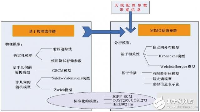
Figure 1. Classification of channel models
An important feature of the GSCM class channel model is that the antenna can be separated from the propagation environment [8]. In contrast, the channel model based on the correlation matrix cannot separate the channel from the antenna characteristics, so in principle it cannot be used to reconstruct the channel for testing terminal performance. Model - but the TGn model [7] is based on a correlation matrix, which contains a description of the geometric information, which makes it possible to reproduce TGn in the MIMO OTA. In other words, in the MIMO OTA multi-probe method, the reconstruction of the channel is based on the characteristics of the respective incoming waves, which can have their respective delays, Doppler shift, angle of arrival (AoA), and exit angle ( AoD), etc., after synthesis, the spatial correlation of the channel and the Doppler spectrum related to the channel geometry will be reflected on the terminal antenna element array. The chip will analyze and optimize these channel characteristics, which will eventually affect the terminal performance. . [3][4][5] [6] are all such channel models.
1.2, SCM and SCME models
Referring to modern MIMO channel modeling, especially the GSCM channel model, we have to mention the 3GPP SCM (SpaTIal Channel Model) model [3] and the European WINNER (Wireless World INiTIative NEw Radio) project [5]. Among the SCM models described in 3GPP TR25.996 in 2003, the traditional TDL (Tap Delay Line) model is further parsed into a CDL (Cluster Delay Line) model described by clusters. Six bundles of waves are defined in the SCM. Each bundle is called a cluster. Each cluster consists of 20 sub-paths. Each cluster has its own AoD and AoA. According to the conclusion of the actual channel test, the energy distribution on the horizontal plane is defined, such as the Laplacian distribution, that is, the Power Azimuth Spectral (PAS), and the variance is defined as the angular expansion (AS, Angular Spread); Each cluster model has its own characteristics such as AoA, AoD, time delay, and Doppler spectrum. The SCM is close to the measured data, and can reflect the characteristics of the MIMO channel from the time domain, the frequency domain, the spatial domain and the polarization domain. The parameters of the SCM model are introduced in Figure 2 [3].
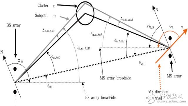
Figure 2. Channel model and its parameters in 3GPP TR 25.996
Description of the parameters in 3GPP TR 25.996:
ΩBS: The direction of the antenna array of the base station, with the geographic north as the reference direction, defined as the angle between the normal of the antenna array and the north direction.
θBS: The line of sight (LOS) of the base station and the mobile station (AoD, Angular of Departure) is defined as the angle between the direct path and the base line of the base station antenna array.
Δn, AoD: The nth (n = 1 ... N) path starting angle AoD is defined as the angle with its LOS AoD.
Δn,m,AoD: the mth (m = 1 ... M) of the nth diameter relative to δn, the offset of AoD.
Θn,m,AoD: The absolute AoD of the mth sub-path of the n-th path, defined as the angle with the base line of the base station antenna array.
ΩMS: The direction of the antenna array of the mobile station, with the geographic north as the reference direction, defined as the angle between the normal of the antenna array and the north direction.
θMS: the angle between the base station and the mobile station LOS and the normal direction of the mobile station antenna array.
Δn, AoA: The nth (n = 1 ... N) Angular of Arrival, defined as the angle with its LOS AoA.
Δn,m,AoA: the mth (m = 1 ... M) of the nth diameter relative to δn, the offset of AoA.
Θn,m,AoA: The absolute AoA of the mth sub-path of the n-th path, defined as the angle with the normal to the antenna of the mobile station antenna.
v : The moving speed vector of the mobile station.
Θν : velocity vector angle, defined as the angle between the direction of motion of the mobile station and the normal direction of the antenna array: θν = arg (v).
With the continuous development of communication technology, the increase of bandwidth increases the resolution of the channel delay of the system, which causes the change of frequency domain correlation. The channel established by the CDMA system of 5MHz bandwidth in the original 3GPP SCM model is established at 2GHz operating frequency. The model appears to be insufficient. That is to say, for the improvement of bandwidth, some improvements are needed to make the influence of bandwidth variation on channel correlation in the channel model. In 2005, channel researchers from Switzerland, Germany, and Finland proposed an extended model SCME that is forward-compatible with the SCM model in [9], which better adapted to the requirements of the channel model brought by the new technology. In general, the wider the bandwidth of the system, the more the number of delays that can be recognized as the number of delays, that is, the default path in the channel model experiences Flat Fading. Therefore, the 5MHz defined for the SCM model. The 6-path model under bandwidth, the SCME model expands each path to three paths (Mid-Path), enabling the channel model of a wider bandwidth system to exhibit frequency-selective fading, or to increase each path. The delay extension. A comparison between the SCM, SCME and WINNER channel models can be found in [10].
Referring to the parameter definition in Figure 2, the SCM model Channel Impulse Response (CIR) can be mathematically derived as follows, similar to MIT's old professor RG Gallager in references [11] and David Tse in Ref. [12]. In general, the transmission matrix (impact response) of a linear time-varying system MIMO channel can be described as the sum of the impulse responses of one path, namely:
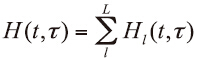 (1)
(1)
It consists of the response matrix Frx(RX), Ftx(TX) and impulse response matrix hl of the transceiver antenna array:
![]() (2)
(2)
Considering the dual polarization, the channel impulse response of the 1st path is a 2 × 2 polarization matrix:
 (3)
(3)
When we use the CDL model, the first path in equation (3) replaces the mth sub-path in the nth cluster [8], and further, the transmit antenna unit s of the m-th sub-path of the n-th cluster is received. The channel modeling between antenna elements u is expressed as (4):
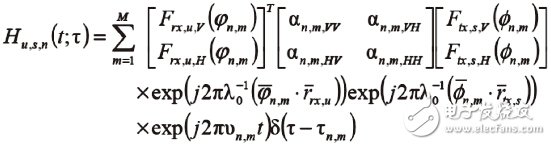 (4)
(4)
In 1963, Bello [20] studied the time-varying impulse response and the transfer relationship between the transfer function and the channel correlation function under the premise of the generalized stationary non-correlation environment (WSSUS), and became the theoretical basis of channel measurement and verification. .
1.3, MIMO channel parameters
In this section, we introduce the main parameters used to describe the characteristics of MIMO channels based on the concept of geometric random channel model. They are PDP (Power Delay Profile), Doppler spectrum, and Spatial Correlation. And the cross-polarization ratio (XPR) of the channel. Since these four parameters characterize the important characteristics of the MIMO system in the frequency, time, space and polarization domains of the channel, they are considered to represent or cover the main features of the MIMO channel, so they are also adopted by CTIA and 3GPP as MIMO OTA. The four main parameters of the system verification [13][14][15].
1.3.1, Delay Feature (PDP, Power Delay Profile)
For a linear time-varying channel, the impulse response of a channel can be described by its autocorrelation function. However, for the purpose of simplification, in a large number of MIMO channel measurement processes, the delay power spectrum is often used to describe the signal. The energy distribution of the simultaneous delay, Figure 3 is the PDP spectrum of a standard SCM Urban Macro Cell (UMa, Urban Macro) channel model.
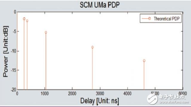
Figure 3. 3GPP SCM UMa delay characteristics
The PDP embodies the different delays that the receiver can discern when the signal arrives at the receiver through different propagation paths, and its delay spread reflects the frequency selective fading bandwidth of the channel, or determines the channel's correlation bandwidth.
1.3.2, Doppler spectrum
The Doppler shift reflects the effect of the received signal on the received signal in the time domain fading due to the direction and velocity of the receiver relative to the incoming wave. RHCarke was elaborated in 1968 in Ref. [16]. The so-called classical Doppler spectrum refers to the "U" spectrum of the Clarke model. In the MIMO channel model, since each path is composed of multiple sub-paths, each sub-path contributes to the Doppler spectrum of the receiver signal, and the Doppler spectrum of the final channel will be The diameter of the approach angle and its angular extension are related.
The Doppler spectrum in the channel model actually reflects the fastness of channel fading, ie fast fading or slow fading. It describes the evolution characteristics of the channel in the time domain and determines the correlation time of the channel.
1.3.3 Spatial correlation
The spatial correlation embodies the correlation between the antenna elements at the receiving end. This spatial correlation is more specific in the CDL. In most cluster-based CDL channel models, each path has actually been replaced by a cluster, each cluster has an independent uniform angle of arrival (AoA), and each sub-path has a slightly different angle of arrival. Shift, as mentioned above, the probability distribution effect of the sub-paths in different statistical angles of arrival is reflected by the angular power spectrum PAS in the channel model. According to the actual test results, the shape of the PAS is generally close to the energy of the cluster AoA. (or probability) is large, and is far from AoA. A widely used distribution model in the SCM model is the Laplacian distribution, meaning that the statistical energy distribution of each sub-path arrival angle is centered on AoA. The bilateral index declined.
Reference [17] Based on the angle of arrival of PAS and sub-paths, Spirent's Doug Reed gives a mathematical expression for the spatial correlation between two virtual receiving antenna elements in reference [18]:
 (5)
(5)
For different description purposes, refer to [19], Anite's Pekka also gives a mathematical expression of spatial correlation in reference [8]:
 (6)
(6)
MIMO multi-antenna technology uses airspace non-correlation to improve system performance. Therefore, to evaluate the performance of MIMO terminals, spatial correlation verification is especially important for channel models and MIMO OTAs.
1.3.4, channel cross polarization ratio
There are many definitions of cross-polarization ratio, such as XPR with transmit antenna and XPR for receive antenna, but the XPR currently used in the channel model mainly refers to the parameters of pure channel, which is described in 3GPP37.977:

among them:
SVV is the coefficient between the V-polarized power due to the scattering or reflection of the channel and the V-polarized power at the time of incidence;
SVH is a coefficient between the V-polarized power obtained by scattering or reflection of the channel and the H-polarized power at the time of incidence;
SHV is a coefficient between the H-polarized power obtained by scattering or reflection of the channel and the V-polarized power at the time of incidence;
SHH is a coefficient between the H-polarized power due to scattering or reflection of the channel and the H-polarized power at the time of incidence.
XPR is directly related to the channel characteristics and is also affected by the departure angle AoD in the channel model, which is generally not 1. The XPR is usually different under different channel models. For example, the XPR is 8.31dB in SCM UMa, and the XPR is 0.83dB in SCM UMi. The XPR in different scenarios of WINNERII is different, reflecting the characteristics of various channel environments. In the antenna design and baseband algorithm design of the terminal, it is necessary to use the difference of XPR to do some system performance optimization.
In the narrow space of the terminal, it is necessary to design a pair of antenna elements with good correlation. The polarization ratio is one of the main means. In this sense, the channel model and test method for MIMO OTA should be able to control the channel. XPR, otherwise there will be no important considerations for evaluating the performance of the terminal. In the reference [21], Tommi describes how to generate the XPR required in the channel model as a multi-probe MIMO OTA test scheme.
2. Introduction to MIMO OTA test method
2.1, MIMO OTA Introduction to each test plan
In 3GPP 37.977 [15], there are many alternative MIMO OTA test scenarios, which can be grouped into four categories, each of which is dominated or supported by different companies. This section briefly describes the construction of these scenarios mentioned in 37.977. Method, and some of the legends are cited (in the 3GPP meeting in November 2013, the decomposition method led by R&S was temporarily not included in the 37.977 body).
2.1.1, Multi-Probes based test solution
This test method uses an AC (Anechoic Chamber) to eliminate unwanted reflection of radio waves. The signal of the BaseStation Emulator is experienced by a channel emulator (CE, Channel Emulator, sometimes called Fading Emulator). After defining the channel model, the dual-polarized antenna (ie, multi-probe) that is centered on the DUT (Device Under Test) is transmitted to the DUT through space radiation, so that it undergoes the required channel fading, and observes Record its throughput performance. One typical implementation is shown in Figure 4.
Figure 4. Multi-probe based test protocol in the darkroom
At present, although many companies produce and design channel emulators, only the channel emulators provided by Anite of the United Kingdom and Spirent of the United States can support the MIMO OTA test described in this method. They complete the reconstruction of the channel model and pass through the darkroom. The reconstruction of the spatial domain information by the probe system, so it can be said that in this method, the channel simulator becomes the core of the entire test system. For example, SATIMO in France and ETS-Lingen in the United States provide software support and system integration services for the entire test system. They rely on the technology and system experience established in the traditional OTA certification test, and have foreseen and started the MIMO OTA very early. R&D work, but only when the channel emulator breaks through the technology, the whole system construction becomes clear. At the same time, there are some local system integrators in the country that support the solution, such as Japan Microwave Factory, Korea MTG, domestic HWA. -TECH, etc. System integrators will typically design and implement darkroom, multi-probe antennas, power amplifiers, RF cables, RF switches, and measurement and control software to work with channel simulators. In addition, system integrators should provide system calibration and final system Channel verification service, etc.
Multi-probe schemes require multiple probes to be built across the entire spherical (3D, 3D channel model) or horizontal (2D, 2D channel model) to simulate the signal arrival angle and its angular spread in all directions (cluster); if a 3D channel is to be implemented The model needs to simulate the signal arrival angle and its angular spread in the vertical direction, and the system is more complicated. At the same time, each dual-polarized probe needs to connect two independent channel emulator physical channels, which means that the cost of the multi-probe system will be significant. Higher than other programs, and practice has proved that its calibration and test complexity is also higher than other programs. While bringing cost and complexity, the advantages of multi-probes are equally obvious. This method theoretically reproducibly reproduces the channel model. The channel verification results also prove the prediction of the mathematical model. This test method will be in the future. It is possible to upgrade and develop into a virtual virtual drive (VDT): the external environment experienced by the terminal can be reproducibly reproduced in the laboratory, not only for the needs of certification testing, but also for chip and terminal developers to improve new technologies. The only way for the new algorithm.
The following will focus on the technical details of the multi-probe based method and introduce the research work carried out by the Radio and Television Planning Institute.
2.1.2. Test plan based on two-step method (2-Stage)
The two-step method was first proposed by Agilent's Chinese laboratory in the United States, and has consistently adhered to and perfected their original design philosophy. The so-called two-step method means that the antenna pattern of the terminal is obtained by some method in the first step, and the obtained antenna pattern data is introduced into the baseband channel emulator in the second step, and then the DUT is transmitted. Tested to take into account the overall performance of its baseband chip and antenna, a typical implementation is shown in Figure 5.
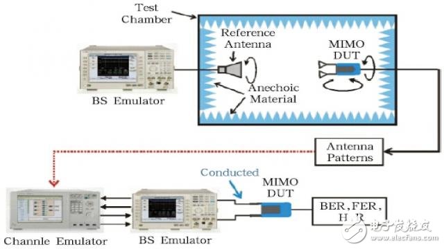
Figure 5. Test plan based on two-step method
In theory, the two-step method is similar to the multi-probe method in that the DUT is placed in a simulated geometric channel model. These channel models can be derived from standard models or custom, but with multiple probes. The method is to reconstruct the channel model in real space by constructing a physical darkroom and multiple probes, and the two-step method is to apply the measured antenna pattern into the baseband channel simulator and apply the DUT to the software through simulation. The impact of fading.
At present, only Agilent in the United States is pushing this test method. The multi-probe based test solution in the darkroom is supported by Qualcomm. In the two-step method, the direction of the antenna obtained through the chip is crucial. An important step, so the method currently requires the chip to provide this test mode. Compared to the multi-probe method, the advantage of the two-step method is that there is no need to build a multi-probe system, which reduces the investment cost and test time cost. However, this method is usually questioned: measuring the performance of a device under test, part of the test data depends on the internal chip of the device itself, which means that the tester must additionally evaluate the chip confidence; On the one hand, the two-step method is currently not supported for new technologies such as Beamforming that improve the performance of the terminal by changing the antenna pattern in real time. The reality is that the "Airport Time Capsule", a wireless bridge product that Apple recently launched in 2013, has already stated that it supports beamforming technology in MIMO [1].
2.1.3. Test plan based on Reverberation Chamber (RC)
The concept of a reverberation chamber is the opposite of a darkroom, which tries to avoid the signal from undergoing reflection before it propagates to the DUT, while the former uses various methods to cause the signal to be reflected as much as possible within the reverberation chamber before being communicated to the terminal. The DUT goes through the so-called Rayleigh channel, and at least two companies claim to provide their own implementations in 3GPP 37.977, see Figures 6 and 7.
Figure 6. Test plan based on reverberation chamber
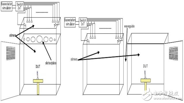
Figure 7. Test plan based on reverberation chamber
The founder of Bluetest is Professor Per-Simon Kildal from Chalmers University of Technology, Sweden. He has been trying to apply reverberation chambers to antenna performance measurements early in the antenna design process. They used the RC measurement method in the traditional single-antenna design and then started to apply it to the MIMO antenna, and made many new definitions [22][23]. In recent years, Per-Simon and his doctoral student Chen Xiaoming gradually proposed The method of active multi-antenna terminal throughput test in the reverberation room is perfected, that is, the RC-based MIMO OTA scheme [24]~[27]. Similarly, the research team led by David Sanchez of Emite in Spain also used the RC scheme for MIMO antenna and terminal testing during the antenna design process and proposed some new ideas for them. In the past few years of domestic customer trials, Bluetest has established a good reputation in product applicability through commercial operations.
Regardless of whether it is a passive single antenna or a passive multiple antenna, the RC test alone is generally based on the efficiency of the RC itself and the reference antenna. For active testing of real terminals, RC can be considered to create a Rayleigh channel condition. The Rayleigh channel is a concept that has been proposed in the era of single-antenna terminals. We can see from the MIMO channel model that the wideband MIMO channel model is parsed in the time domain, the frequency domain, the spatial domain and even the polarization domain. The internal Rayleigh channel established by RC can not reflect the arrival delay of different paths, nor can control the Doppler dispersion of different paths, and can not control the angle of arrival of each path. It can only give the final signal amplitude obeying the Rayleigh distribution. Statistical model. In order to solve the problem of accurately describing the delay characteristics, RC has considered introducing additional delays by adding absorbing materials, but this method has poor controllability, and because the introduction of absorbing materials will change the K factor, the measurement will not be made. The degree of certainty is expanded [27].
In this case, an upgrade scheme for the reverberation room and channel emulator, RC+CE, was proposed. Simply put, the signal is added to the delay and the channel through the channel emulator before entering the reverberation chamber. The Puls frequency shift is used to make up for the shortcomings of the original single RC solution. Although this method solves the problems encountered by RC in delay and Doppler in the analog channel model to some extent, it also weakens the economic advantage of the original single RC while introducing the channel simulator. The information of the spatial domain such as the angle expansion and the angle of arrival is still temporarily undescribed due to the inherent conditions of the reverberation chamber itself. However, because there is no need to describe spatial information, the test speed of the reverberation room scheme is accelerated, and the statistical results are statistically averaged during the test, which makes the test results appear stable, while the reverberation room scheme is spatially correlated with the MIMO system. Sexual verification capabilities, especially polarization discrimination, have declined dramatically. In an experiment conducted by Motorola, Inc., Istvan, the RC proved to be completely incapable of identifying the polarization performance of the terminal [28].
2.1.4. Test scheme based on decomposition method
The MIMO OTA scheme proposed by the German R&S is derived from Professor WL Schroeder of RheinMain University in Germany and his doctoral student Feng Yifei [29]. The schematic diagram is shown in Figure 8.
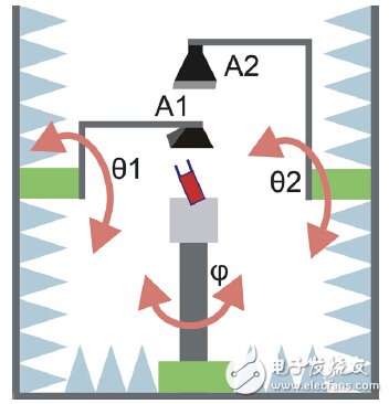
Figure 8. Test solution based on decomposition method (R&S, Germany)
The decomposition method was once called the two-channel method, meaning that during the test, there are two transmitting antennas that send the signals of the base station simulator to the DUT, the DUT rotates in the horizontal plane, and the two probes move simultaneously on the vertical plane, they first One problem encountered was the choice of DUT test position (angle) and transmit antenna position.
In addition, R&S engineers claim that this method differs from the multi-probe full-loop approach in that “the decomposition method is a 3D test method and the multi-probe full-loop only performs the horizontal 2D testâ€, but in reality, first they misinterpret the 3D channel. The concept of the model, on the other hand, even at the same time, at the same time, the two transmit antennas and the DUT are actually on the same plane.
In a November 2013 meeting of the 3GPP RAN4, this method was not included in the text.
2.2. Multi-probe scheme international research dynamics and evolution
From the perspective of test methods, researchers based on channel emulators and darkrooms and multi-probes have done a great deal of research independently from each other: Pekka Kyösti of Finland elaborated the multi-probe scheme in reference [8]. The principle consists of two signal synthesis methods: Wave Field Synthesis (WFS) and Pre-Faded Signal Synthesis (PFS). John Douglas Reed of Spirent, USA, describes the use of MIMO in Reference [30]. OTA's approach reproduces spatial correlation; Professor Gert Pedersen of Aalborg University in Denmark led his team to collaborate with Intel to build a darkroom, multi-probe and test software, and tested the LTE terminal test method for channel models such as SCME. Research, and the test results of the multi-probe scheme system configuration and verification [31] ~ [33]; American Apple company Matt A. Mow et al. Comparison of the consistency of the terminal in the MIMO OTA test process and conduction test Methods were studied and patents were applied [34]. The number of multi-probes for plane wave synthesis was studied by the former Helsinki University in Finland, Tommi Latinen et al. [35]; studies by Matsushita and Tokyo Institute of Technology have proved that the use of channel simulators and multi-probe methods can produce accurate RF channel models, thus It is possible to study the MIMO channel capacity using controllable spatial correlation [36]. They also give suggestions for system design and calibration procedures [37]; British Anite (formerly Elektrobit) has launched very early. The feasibility study of MIMO OTA test compares the simulation and measured results with the characteristics of the reference model. The results show that OTA and the reference model are highly consistent in most cases, which proves that the required wireless can be generated in the darkroom. Channel propagation characteristics [38].
From the perspective of the channel model, the ray-based multi-antenna channel model began to transition from Tap Delay Line to Cluster Delay Line in 2000. The SCM was defined in 3GPP TR 25.996 in 2003. The European WINNER project further promotes and refines the basis. The development of a geometric random channel model GSCM. At present, although each MIMO OTA solution claims to be superior, it is an indisputable fact that the multi-probe channel model is recognized by industry and academia earlier than the MIMO OTA solution, while several other test solutions are There are not many radio wave propagation and channel models, and on the other hand, they are aligning their test results with multi-probe systems.
Beginning in 2008, there are three academic and standardization organizations around the world that focus on multi-input and multi-channel channel testing, modeling, and MIMO OTA testing. They communicate and discuss the above technologies and topics in their respective areas. They are:
1 . COST2100 and its successor IC1004 under European COST (European COoperation in Science and Technology)
2. North American CTIA (Cellular Telephone Industry Association)
3. “Third Generation Partnership Project†(3GPP)
In the current MIMO OTA test methods appearing in the discussion of COST IC1004, 3GPP and CTIA, the author believes that the scheme based on channel emulator and darkroom multi-antenna probe can depend on the performance of MIMO system defined in the SCM channel model. The angle is extended by AS (Angle Spread), and the delay spread DS (Delay Spread) is controlled and reproduced. Other solutions, such as reverberation room testing, can be quickly tested, but cannot control and restore information that has a significant impact on multi-antenna system performance, such as angular expansion, so it can only provide limited performance evaluation for the terminal; The original SISO microwave darkroom can be used to reduce the investment, but the tested equipment needs to support the test mode, and new technologies such as future beamforming cannot be supported at present; the decomposition method no longer retains the original channel model concept, and uses statistics. The method estimates the performance of the MIMO system, and the correspondence between the test data and the real environment is also lacking in data support.
However, the ultimate goal of the multi-probe test solution is to implement a 3D signal model. This requires a sufficient number of darkroom and antenna probes. On the other hand, the channel simulator is required to provide sufficient physical channels, making the multi-probe 3D solution expensive. Hard to get in place. A step-by-step approach is to use a single cluster method as a starting point to create a scalable multi-probe system. Referring to the description in 3GPP 37.977, Figure 9(a) describes the multi-cluster method and (b) describes the single-cluster method.

Figure 9. Multi-probe test protocol: multi-cluster method and single-cluster method
In short, in the widely used 2D full-loop multi-cluster test scheme, the performance characteristics of the terminal under different channel delay characteristics, Doppler spectrum, spatial correlation and cross-polarization ratio can be considered, but Since the channel model is limited to the horizontal plane, it is impossible to describe the influence of the incoming wave from the vertical direction on the performance of the terminal; similarly, in the single-cluster method, the delay characteristics and Doppler spectrum of the terminal in different channels can also be considered. Performance evaluation under spatial correlation and cross-polarization ratio, but because it is limited to a single cluster, it is impossible to describe the incoming waves from different clusters; in this sense, the multi-cluster of the full-loop method, and the single-cluster test The method is a compromise between the multi-probe 3D method.
3. Progress of ABP work
The Broadcasting and Television Planning Institute (ABP) has been involved in the research of multi-antenna terminal test methods since 2011. At present, the multi-probe MIMOOTA test system with single-cluster method has been established, which not only verifies each component [39], but also the entire system. The final channel model was validated and, in 2013, participated in the CTIA organization's comparison test [40]. This section will focus on this aspect.
3.1, ABP single cluster method MIMO OTA system
The connection diagram of the single cluster method laboratory of the Radio and Television Planning Institute is shown in Figure 10. The biggest feature of this scheme is the modification of the original conventional single-antenna terminal OTA test darkroom (ETS AMS8600). The dimensions of the darkroom are shown in Table 1. Since there is no need to build another darkroom, not only the cost of system construction is greatly reduced, but also the trouble of another darkroom addressing is eliminated. On this single-cluster MIMO OTA technology platform, basic research on most multi-probe systems including channel verification has been advanced.
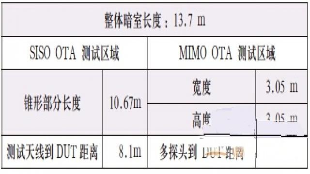
Table 1, ABP darkroom data
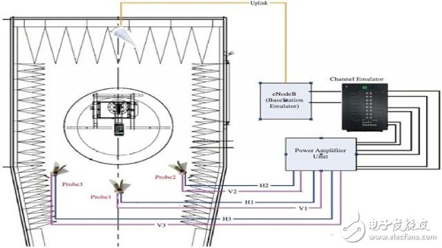
Figure 10. Radio and Television Planning Institute (ABP) Single Cluster Method MIMO OTA Test System
With a special design, the system can convert between MIMO OTA and regular OTA tests. This conversion takes about 5-10 minutes for two people, as shown in Figure 11, so the system can balance the conventional antenna/terminal OTA test with MIMO OTA testing of multiple antenna terminals.

Figure 11. Switching between single-cluster MIMO OTA and SISO OTA test environments
3.2. Verification of the system and various components
3.2.1 Darkroom characteristics change
As mentioned above, ABP's single-cluster MIMO OTA is built on the basis of the SISO darkroom. By setting the antenna support in the darkroom, the two test modes can be switched in a short time, but compared to the original SISO darkroom. The added components may affect the characteristics of the darkroom, so we performed the ripple test in both environments according to the requirements of CTIA, and completed the comparison of the 30cm radius in free space and the 50cm radius in the two frequencies. The results are shown in Table 2 and Table 3.
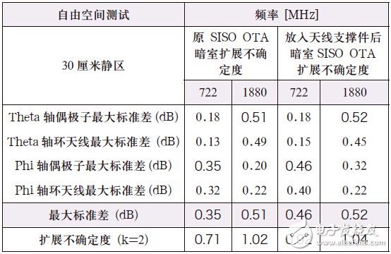
表2ã€SISO 暗室的纹波测试比对验è¯ï¼ˆ30cm é™åŒºï¼‰
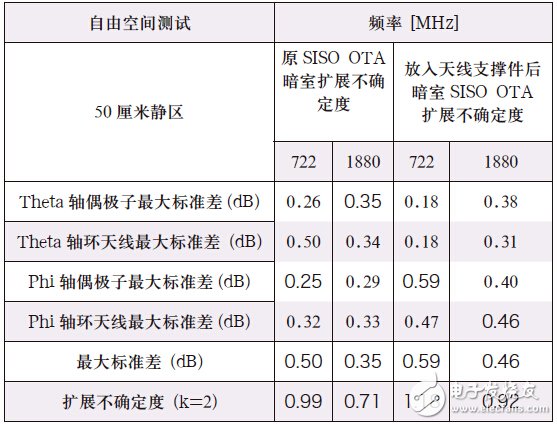
表3ã€SISO 暗室的纹波测试比对验è¯ï¼ˆ50cm é™åŒºï¼‰
测试结果表明扩展ä¸ç¡®å®šå‡ 乎没有太大å˜åŒ–ï¼Œå¢žåŠ å¤©çº¿æ”¯æ’‘æž¶åŽè¿›è¡ŒSISO OTA 测试的暗室环境的扩展ä¸ç¡®å®šåº¦ä»ç„¶æ»¡è¶³CTIA å°äºŽ2 çš„è¦æ±‚。
3.2.2ã€ä¿¡é“仿真器特性åŠä¿¡å·æ¼‚移
ä½œä¸ºæ ¸å¿ƒéƒ¨ä»¶ï¼Œä¿¡é“仿真器的特性æžå¤§åœ°å½±å“ç€æ•´ä¸ªç³»å›¾10 广æ’电视规划院(ABP) å•ç°‡æ³•MIMO OTA 测试系统统的ä¸ç¡®å®šåº¦ï¼Œæˆ‘们需è¦çŸ¥é“ä¿¡é“仿真器设置åŠè¾“入信å·å¯¹äºŽè¾“出信å·çš„å½±å“程度;åŒæ—¶ï¼Œä¿¡é“仿真器作为一个有æºè®¾å¤‡ï¼Œå–决于内部部件的质é‡ï¼Œå…¶è¾“出信å·çš„幅度与相ä½å‡å¯èƒ½ä¼šéšçŽ¯å¢ƒï¼ˆæ¸©åº¦ã€æ¹¿åº¦ï¼‰å‘生ä¸åŒç¨‹åº¦çš„漂移,如果漂移情况严é‡ï¼Œä¿¡é“仿真器将会对整个系统的ä¸ç¡®å®šåº¦äº§ç”Ÿå½±å“。
我们在两个工作日分别åšäº†ä¸åŒçš„输入功率下,一分钟内信å·ä»¿çœŸå™¨çš„输出信å·å¹…度与相ä½çš„å˜åŒ–测试,最æ¶åŠ£çš„结果记录在表4 ä¸ï¼Œæ¤å¤–对两个工作日的输出信å·åšæ¨ªå‘比较,以便了解长期情况下,其信å·çš„æ¼‚ç§»æƒ…å†µã€‚æ ¹æ®æµ‹è¯•ç»“果,推èçš„æ“作是:进行MIMO OTA 测试时,应维æŒåŸºç«™æ¨¡æ‹Ÿå™¨çš„输入功率ä¸å˜ï¼Œæ ¹æ®ä¿¡é“仿真器设置,推è输入功率的范围如下:
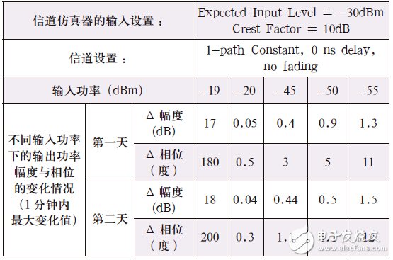
表4ã€ä¿¡é“仿真器的输入设置对系统稳定性的影å“
(EIL-20) ≤INPUT ≤(EIL+CE) (7)
也å³è¾“入功率应该尽é‡æŽ¥è¿‘期待功率(EIL),其å˜åŒ–范围最å°åº”大于设置的期待功率20dB以上,最大则ä¸èƒ½æ¯”设置的期待功率的峰å‡æ¯”(CF)更大,å¦åˆ™ç³»ç»Ÿçš„ä¸ç¡®å®šå°†å¢žå¤§ã€‚对于信é“仿真器的信å·æ¼‚移,在符åˆå¼ï¼ˆ7)的情况下,表5 的测试结果è¯æ˜Žä¿¡é“仿真器输出信å·çš„幅度漂移ä¸è¶…过0.1dB,相ä½å˜åŒ–ä¸è¶…过1.5 åº¦ï¼Œå› æ¤æˆ‘们å¯ä»¥è®¤ä¸ºä¿¡é“仿真器在整个测试过程ä¸æ˜¯è¾ƒä¸ºç¨³å®šçš„。
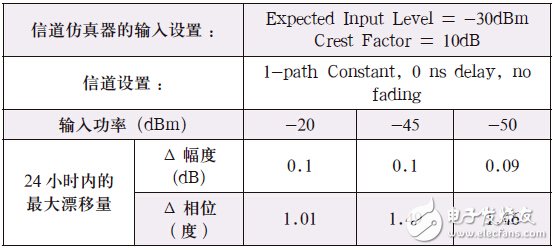
表5ã€ä¿¡é“仿真器信å·æ¼‚ç§»ç ”ç©¶ï¼ˆé•¿æœŸï¼‰
3.2.3ã€åŠŸçŽ‡æ”¾å¤§å™¨ç‰¹æ€§åŠä¿¡å·æ¼‚移
用于补å¿è·¯å¾„è¡°å‡çš„功率放大器其通é“数与信é“仿真器相åŒï¼Œå…¶ç‰¹æ€§åŒæ ·å¯¹æ•´ä¸ªç³»ç»Ÿçš„ä¸ç¡®å®šåº¦äº§ç”Ÿå½±å“。通常,功率放大器需è¦æœ‰30 分钟的预çƒæ—¶é—´ï¼Œåœ¨è¿™æ®µæ—¶é—´å†…,其输出信å·å¹…度å¯èƒ½æœ‰0.5dB~1dB çš„å˜åŒ–,30 分钟åŽè¾“å‡ºå°†è¶‹ç¨³ï¼Œå› æ¤æˆ‘们推è整个系统的预çƒæ—¶é—´ä¸€èˆ¬åœ¨30 分钟,之åŽå†åšæ‰€æœ‰å…¶ä»–的验è¯æˆ–测试工作。
在开始测试之å‰ï¼Œå¿…须获å–功率放大器的线性工作区间,我们对所用到的功率放大器进行了四个频点ä¸åŒè¾“入功率的测试,其增益测试结果è§å›¾12,从图ä¸å¯ä»¥çœ‹å‡ºè¾“入功率大于-30dBm 时将é€æ¸è¿›å…¥1dB åŽ‹ç¼©ç‚¹ï¼Œå› æ¤æˆ‘们所有åŽç»å·¥ä½œä¸ï¼Œå°†ä½¿å¾—功率放大器的输入功率控制在-30dBm 以下。
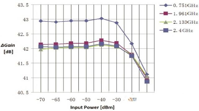
图12ã€åŠŸçŽ‡æ”¾å¤§å™¨çš„增益åŠçº¿æ€§èŒƒå›´
功率放大器的长期信å·æ¼‚移是æ述对应于实验室在两个工作时段,这决定了实验室是å¦èƒ½å¤Ÿåœ¨å‡ å‘¨ç”šè‡³å‡ ä¸ªæœˆæ—¶é•¿å†…ï¼Œæ²¿ç”¨åŒä¸€ä¸ªæ ¡å‡†æ•°æ®ã€‚我们的摸底测试是在两个工作日,对功率放大器分别é‡æ–°å¯åŠ¨ã€é¢„çƒ30 分钟之åŽï¼Œè¾“入设置统一分别设置为-40dBm(线性区间之内),测试功率放大器的å…个通é“,在ä¸åŒçš„频率点的输出信å·å¹…度与相ä½çš„差异值,测试结果è§å›¾13,测试结果表明两次测试功率放大器最大的信å·å¹…度漂移å¯èƒ½è¶…过1dB,相ä½æ¼‚移则相对较å°ï¼Œè¿™æ„味ç€ç³»ç»Ÿåœ¨ä¸åŒçš„工作时间,测é‡ä¸ç¡®å®šå¯èƒ½ä¼šç”±äºŽåŠŸçŽ‡æ”¾å¤§å™¨çš„ä¿¡å·æ¼‚ç§»è€Œå¤§å¹…å¢žå¤§ï¼Œå› æ¤æˆ‘ä»¬å»ºè®®ç³»ç»Ÿåº”è¯¥è¿›è¡Œæ—¥å¸¸æ ¡å‡†å·¥ä½œï¼Œå³æ ¡å‡†æ–‡ä»¶éœ€è¦ç»å¸¸è¿›è¡Œæ›´æ–°ã€‚
功率放大器的çŸæœŸä¿¡å·æ¼‚移是æ述对应于æŸä¸€æ¬¡æµ‹è¯•è¿‡ç¨‹ä¸ï¼Œå¦‚40 分钟,输出信å·çš„å˜åŒ–,我们记录到40 分钟最大的信å·å¹…度å˜åŒ–在0.1dB 以下,这è¯æ˜Žåœ¨åŒä¸€æ¬¡æµ‹è¯•è¿‡ç¨‹ä¸ï¼ŒåŠŸçŽ‡æ”¾å¤§å™¨çš„ä¿¡å·æ¼‚移ä¸ä¼šå¯¹ç³»ç»Ÿæµ‹è¯•ç»“果产生影å“。
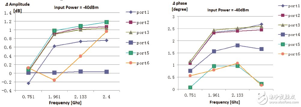
图13ã€åŠŸçŽ‡æ”¾å¤§å™¨å„通é“çš„ä¿¡å·æ¼‚移(长期)
3.2.4ã€å¤šæŽ¢å¤´ä¹‹é—´çš„耦åˆæƒ…况
对于多探头系统,天线探头之间的互相耦åˆå¯èƒ½ä¼šå½±å“到测试结果,这ç§å½±å“的评估在尺寸较å°çš„暗室é…ç½®ä¸æ˜¾å¾—更为é‡è¦ï¼Œåœ¨ABP MIMO OTA å•ç°‡æ³•ç³»ç»Ÿä¸ä½¿ç”¨åˆ°äº†3 个åŒæžåŒ–的天线探头,我们分别对3 个天线的两ç§æžåŒ–åšäº†æµ‹è¯•ï¼Œæµ‹è¯•ç»“æžœè§å›¾14,测试结果表明最大的耦åˆå‘生在3 å·å¤©çº¿çš„垂直与水平æžåŒ–之间,在1.2GHz 约为-18dB,其他耦åˆä¸€èˆ¬å°äºŽ-30dB。
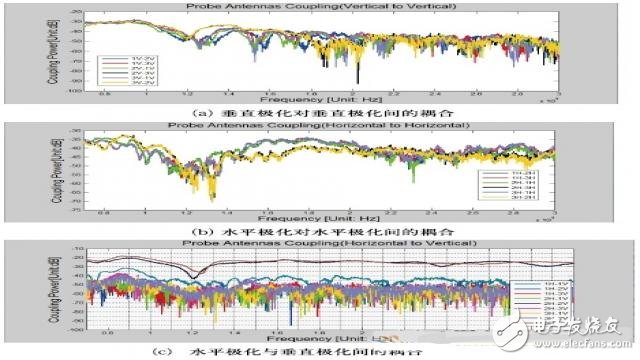
图14ã€æš—室内天线探头之间åŠå„æžåŒ–æ–¹å‘çš„ä¿¡å·è€¦åˆæƒ…况
3.3ã€ä¿¡é“模型的验è¯
作为系统信é“环境é‡å»ºæˆåŠŸä¸Žå¦çš„é‡è¦ç¡®è®¤ï¼Œåœ¨æ£å¼å¼€å§‹æµ‹è¯•ä¹‹å‰ï¼Œæ— 论是何ç§æµ‹è¯•æ–¹æ³•ï¼Œå‡åº”当对暗室/ æ··å“室内部的信é“模型åšä¸€ä¸ªå®Œæ•´çš„验è¯ã€‚广æ’电视规划院对å•ç°‡æ¨¡åž‹çš„ä¿¡é“验è¯ç»“果在å‚考文献[40ï¼½ ä¸æœ‰è¯¦ç»†çš„介ç»ï¼ŒPDPã€å¤šæ™®å‹’频移和空间相关性验è¯çš„结果è§å›¾15ã€è¡¨6 åŠå›¾16。
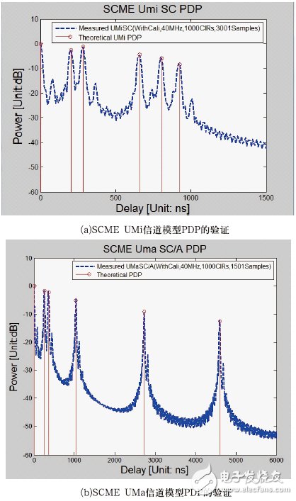
图15ã€ABP å•ç°‡æ³•ä¿¡é“模型的验è¯ï¼šæ—¶å»¶ç‰¹æ€§
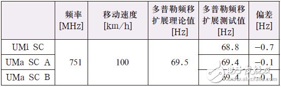
表6ã€å¤šæ™®å‹’扩展的验è¯ç»“æžœ
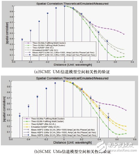
图16ã€ABP å•ç°‡æ³•ä¿¡é“模型的验è¯ï¼šç©ºé—´ç›¸å…³æ€§
3.4ã€æµ‹è¯•åŒºåŸŸå†…çš„ä¿¡å·åŠŸçŽ‡ä¸ŽSIR 验è¯
在目å‰çš„MIMO OTA 针对åžåé‡æµ‹è¯•ï¼Œå¿…须对测试区域内的å‚考测试信å·åŠŸçŽ‡ï¼ˆRS-EPRE)åŠSIR 值进行验è¯ï¼Œå¦åˆ™ä¸åŒå®žéªŒå®¤ä¹‹é—´çš„测试数æ®æ— 法进行统一和比较。å‚考文献[41ï¼½ã€ï¼»42ï¼½ã€ï¼»43ï¼½ ä¸åˆ—举了测试功率åŠSIR 的定义和验è¯æ–¹æ³•ã€‚
广æ’电视规划院的å•ç°‡MIMO OTA 系统的信å·åŠŸçŽ‡ä¸ŽSIR 验è¯ç»“果在å‚考文献[39ï¼½ ä¸å·²åˆ—举,摘录如下:在测试区域ä¸çš„RS-EPRE 的计算值与实际测试值之间差异为-0.34861 dB ;在UMiã€UMa/Aã€UMa/B ä¿¡é“模型下,测试区域ä¸çš„SIR ç›®æ ‡å€¼ä¸Žå®žé™…æµ‹è¯•å€¼ä¹‹é—´çš„å·®å¼‚åˆ†åˆ«ä¸º-0.28dB,-0.58dB åŠ-0.47dB。
3.5ã€å®žé™…测试结果
在CTIA 开展的第二轮比对测试当ä¸ï¼Œå¹¿æ’电视规划院利用建立的å•ç°‡æ³•MIMO OTA 测试系统对é€æ ·çš„3 类天线åŠå…¶ç»ˆç«¯è¿›è¡Œäº†æµ‹è¯•ï¼Œæµ‹è¯•ç»“果表明å•ç°‡æ³•å¯ä»¥å¾ˆå¥½åœ°å°†3 个终端进行区分,ä¸åŒçš„ä¿¡é“模型对终端åžåé‡çš„å½±å“也清晰å¯è¾¨ï¼ˆå›¾17) 。
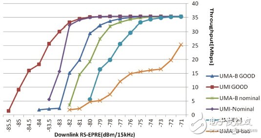
图17ã€ABP å•ç°‡æ³•å®žæµ‹ç»“æžœ
4 Conclusion
在本文当ä¸ï¼Œä»¥å¤šæŽ¢å¤´æ–¹æ¡ˆä¸ºä¸»ä»‹ç»äº†å„ç§å¤šå¤©çº¿ç»ˆç«¯çš„测试方法,并é˜è¿°äº†ä¿¡é“模型åŠå…¶éªŒè¯åœ¨å¤šå¤©çº¿ç»ˆç«¯çš„性能评估方案ä¸çš„é‡è¦æ„义,对以å•ç°‡æ³•ä¸ºä»£è¡¨çš„å¤šæŽ¢å¤´æ–¹æ¡ˆåœ¨ç³»ç»Ÿæ ¡å‡†ã€ä¿¡é“验è¯ã€æµ‹è¯•æ–¹æ³•ç‰ç»†èŠ‚进行了详细的论述。
ä¸å›½çš„4G 牌照已于2013 å¹´12 月4 æ—¥å‘放,多天线终端和MIMO 技术将é€æ¸æˆä¸ºä¸»æµï¼Œä¸Žæ¤åŒæ—¶ï¼Œéšç€å›½å®¶åœ°é¢æ•°å—电视的推广和高清多å±äº’动的应用,以802.11ac 为代表的WiFi 多天线技术也将进入普通家åºã€‚在这个背景下,MIMO OTA 作为ä¿éšœç”¨æˆ·ä½“éªŒçš„ç»ˆç«¯æ€§èƒ½è¯„ä¼°æ–¹æ³•ï¼Œå…¶ç ”ç©¶å’Œæ¼”è¿›å¿…ç„¶å¯¹æ•´ä¸ªæ— çº¿é€šä¿¡è¡Œä¸šåŠå¤šå¤©çº¿æŠ€æœ¯çš„å‘展产生é‡è¦å½±å“。
The insulated terminal is actually a piece of metal sealed inside the insulating plastic. There are holes at both ends to insert the wire. There are screws for fastening or loosening. For example, two wires, sometimes need to be connected, sometimes need to be disconnected. They can be connected by terminals and can be disconnected at any time without having to solder or entangle them, which is convenient and quick. And very beautiful, the cabinet does not look so messy, with an orderly wiring.
classification
Round pre-insulated terminal, cold-pressed terminal block, electric power fitting, fork-shaped pre-insulated terminal, pin-shaped pre-insulated terminal, chip-shaped pre-insulated terminal, bullet-shaped fully insulated terminal, elongated intermediate joint, short intermediate joint, round Bare end, fork-shaped bare end, male and female pre-insulated terminal, tubular pre-insulated terminal, tubular bare end, pin-shaped bare end, peephole series SC, DTG copper terminal, C45 special terminal range insulated terminal Also known as cold-pressed terminals, electronic connectors, air connectors are attributed to cold-pressed terminals.

Insulated Terminal Connector,Ring Terminals,Heat Shrinkable Butt Connectors,Shrinkable Fork Terminals
Ningbo Bond Industrial Electric Co., Ltd. , https://www.bondelectro.com