The 12dBi linearly polarized antenna is most often used with a microstrip antenna array, which is 580 mm × 260 mm × 50 mm. In this paper, a novel form, monopole antenna array, is used for design.
This article refers to the address: http://
1 Analysis and selection of design schemes
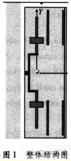
In the design of the 12 dBi linearly polarized antenna, the single-pole oscillator array is used in a novel form, which is the biggest innovation of this antenna. Compared with the microstrip antenna array form, it has the characteristics of strong directivity, small size, light weight and low cost. The overall structure is shown in Figure 1. The monopole antenna of the antenna is constructed by setting one arm length of the dipole antenna to 0 and directly feeding the feed, and the other arm is vertically erected. The designed monopole antenna is one-quarter wavelength long, which produces resonance and the resonant resistance matches the general transmission line feed. Matching and efficiency become a serious problem when the length ratio is much smaller than a quarter wavelength, and the radiation of the feeder section will degrade the overall pattern characteristics.
The current and charge distribution of the monopole antenna is the same as that of the upper arm of the corresponding symmetrical oscillator. However, the input voltage and input impedance are half of the corresponding symmetrical oscillators, and the maximum radiation intensity is the same, but the radiation field is only distributed in the upper half space. The radiant power and the average radiant intensity are half that of the corresponding symmetrical vibrator, so the directional coefficient is twice that. The actual ground finite conductivity reduces the uplift strength of the main lobe and reduces the radiation efficiency. Therefore, the effective gain of a quarter-wave monopole antenna is usually lower than that of a half-wave oscillator antenna. The gain of a single monopole antenna in this antenna is approximately 2 dB. Add a director to the front of the monopole antenna for increased gain. Theoretically, the director is spaced from 0.15 λ to 0.4 λ, and the gain will drop rapidly when >0.4 λ. The length of the director is usually 0.41 λ~O.46 λ, and the phase of the induced current leads the active oscillator π~2π or the lag 0~π, so the field along the direction of the excitation to the director is larger than the field in the opposite direction. Increase gain and enhance directionality. Since the induction current is fed to the induction, the magnitude of the induced current is smaller than that of the active oscillator. Increasing the number of directors can increase the gain, but as the director moves away from the active oscillator, the amplitude of the induced current gradually decreases, and the phase also lags behind, so that the slow-wave surface wave propagates in the axial direction. The longer the axial direction, the more the deflector, the sharper the direction, the higher the gain, and the farther the action distance. However, the improvement effect is not obvious after more than 4 directors, and the volume, weight and production cost are greatly increased, and at the same time The working frequency band is narrower. Consider the above factors by adding two directors to increase the gain. By appropriately adjusting the length of the director and the distance from the monopole, the traveling wave phase velocity can satisfy the enhanced directional condition to obtain the maximum directivity coefficient. When the pitch is large, the impedance is high, the impedance is the lowest when the pitch is 0.15 λ, and the impedance is high when the pitch is 0.2 λ to 0.25λ, and the efficiency is improved. The more the number of cells, the shorter the optimal length of the director. To obtain a wider working frequency band, the length of the director should be shorter.
The antenna is mounted by a pole, and the pole is made of metal iron, which actually functions as a reflector: effectively eliminates the back lobes of the antenna pattern, and enhances the sensitivity of the antenna to the front signal together with the director to make it extremely strong. Directionality, thereby increasing gain. After a monopole antenna plus a director and a pole, the gain in the main radiation direction is approximately 9 dB. Two monopole antenna arrays are used to achieve 12 dB gain. The cell factor depends only on the type and orientation of the cell, which is equal to the normalized directional map function at the coordinate origin monopole antenna. The array factor depends only on the shape, spacing, amplitude and phase of the excitation current, and is equal to the pattern of the isotropic point source array having the same position, the same current amplitude and phase as the actual array. The antenna adopts an equal amplitude in-phase binary array with a pitch. When the two cell spacing > λ, the pattern will appear multiple lobes.
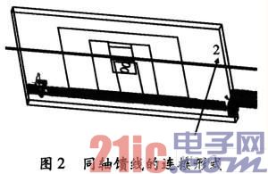
Since the RFID system has an impedance of 50 Ω, a 50 Ω coaxial line feed is used to achieve matching so that the antenna can absorb all of the incident wave power. Since the shielding layer outside the coaxial line and the direction of the copper core conducting current are opposite, in order to make the two monopole antennas form an equal amplitude in-phase binary array, the two coaxial feeding lines are reversely connected, that is, one coaxial line. The copper core is connected to the excitation, the outer shielding layer is connected to the ground, and the copper core of the other coaxial line is connected to the ground, and the outer shielding layer is connected with the excitation, and the form is shown in FIG. 2 . At the same time, impedance matching is performed by the reserved series and parallel matching positions, so that the antenna impedance is about 50 Ω, and the standing wave is <1.2 in the operating frequency band.
The key dimensions that affect the main performance of the antenna are analyzed and illustrated below. The key dimensions of the antenna are as follows: (1) The distance between the pole and the monopole: it has little effect on the gain, only a few tenths of a dB. However, the front-to-back radiation ratio and the input impedance have a great influence, and the gains of the back lobes are significantly different when the pitch is different, so that there is a big difference between the front and back ratios. The magnitude and phase of the current voltage across the reflector is related to the pitch. Because the spacing is different, the spatial distance through which the electromagnetic waves travel is different, and different phase differences are formed. Properly arranging the distance between the reflector and the monopole can cause the electromagnetic field generated by the reflector and the active oscillator to cancel each other behind the reflector and add them on the front side of the active oscillator, thereby suppressing the gain of the back lobes. It can be seen from the simulation results that the smaller spacing can effectively suppress the backward radiation, but the input impedance is low, which is difficult to match well with the coaxial feeder;
(2) Arm width of the monopole oscillator: It can be seen from the simulation that as the arm width of the monopole oscillator increases, the gain increases. The position of the impedance point on the Smith chart increases with the arm width, and moves from the inductive impedance region to the capacitive impedance region counterclockwise along the equal resistance circle, because the increase in the area of ​​the vibrator increases the capacitance gradually. The thickness of the vibrator will also affect the optimal length of the vibrator, because the speed of the electric wave traveling in the metal is not the same as that in the vacuum. The actual length must be subtracted from the theoretical value by a shortening factor, and the thicker the vibrator, the length of the vibrator. The smaller. The theoretical length of the vibrator is λ/4, so the optimal length is smaller than λ/4. From the circuit theory, the conductor whose length is slightly shorter than the integral multiple of λ/4 is capacitive, so the monopole is presented at this time. Sexuality increases the capacitance of the antenna. Moving the impedance point gradually toward the capacitive impedance region on the Smith chart affects the impedance characteristics of the entire antenna. And the arm width is about large, the lower the Q value of the antenna, and the larger the bandwidth;
(3) Spacing of array units: The unit spacing has a great influence on gain and impedance. It can be seen from the simulation data of Table 1 that as the pitch increases, the main lobe gain and the back lobes become larger, that is, the energy in the side-fire direction of the antenna increases. The main beam of the antenna lobe points in a direction perpendicular to the axis of the array as a side shot array. The array spacing d has a limit condition (pointing of the main beam)
d<λ/1+
Aluminium Curtain Wall Profiles
Aluminium Curtain Wall Profiles,Aluminum Extrusion Profiles,Aluminium Profile System,Custom Aluminum Extrusions
KAM KIU ALUMINIUM GROUP , https://www.kamkiualuminium.com