Zener Diode and TVS Tube
Zener Diode (Zener Diode)
Principle: A Zener diode operates in the reverse breakdown region. When the reverse voltage reaches or exceeds the stable voltage, the reverse current increases sharply, while the voltage across the diode remains nearly constant.
Classification:
Based on voltage level: Low-voltage Zener diodes (<40V); High-voltage Zener diodes (>200V).
Based on material type: N-type and P-type.
Main Parameters:
1. Stable Voltage VZ: The voltage at which the Zener diode operates under a specified reverse current IZ.
2. Stable Current IZ: The minimum current required for the Zener diode to maintain regulation.
3. Dynamic Resistance rZ: The resistance of the Zener diode when it is in the breakdown region.
4. Maximum Power Dissipation PZM: The maximum power the Zener diode can handle without damage.
5. Maximum and Minimum Stable Working Currents (IZmax and IZmin): These define the range of current over which the Zener diode can operate effectively.
6. Temperature Coefficient: As temperature increases, the voltage regulation accuracy may decrease.
Usage:
1. Clamping the drain and source.
Silicon Stabilized Diode Regulator Circuit:
This circuit uses the reverse breakdown characteristic of the Zener diode. Due to its steep reverse curve, even a large change in current results in only a small voltage change, making it ideal for voltage regulation.


Transient Voltage Suppressor (TVS)
1. Features:
Under specific reverse conditions, when exposed to a high-energy transient overvoltage pulse, the TVS rapidly reduces its impedance to a very low conduction level, allowing large currents to pass through and clamping the voltage to a predetermined level. This protects sensitive electronic components from damage. It has fast response time (in the ps range), compact size, low clamp voltage, and high reliability. Bidirectional TVS is suitable for AC circuits, while unidirectional TVS is typically used in DC circuits.
2. Classification:
Divided into unipolar and bipolar based on polarity.
3. Symbol:

4. Diode Characteristics Chart:


5. Example of Transient Voltage Suppression and Unidirectional Protection:

6. Main Parameters of TVS:
1. VBR: Reverse Breakdown Voltage. At 25°C, when a 1 mA current flows through the TVS, this is the minimum voltage at which the device begins to conduct.
2. IR: Reverse Leakage Current. Typically ranges from 10–100 μA, important for high-impedance applications.
3. VRWM: Maximum Reverse Operating Voltage. Usually 0.8–0.9 times VBR. Must be higher than the normal operating voltage of the protected device.
4. VC(max): Maximum Clamp Voltage. Under peak pulse current, this is the highest voltage the TVS will allow. The clamp factor is about 1.3.
5. Cj: Junction Capacitance. Affects the response time and signal integrity, especially in high-frequency circuits.
6. IPP: Maximum Peak Pulse Current. The highest current the TVS can handle during a surge.
7. PPR: Peak Pulse Power. Depends on IPP, VC(max), and environmental factors.

7. TVS Diode Nomenclature:

8. Testing a TVS Diode:
Use a multimeter in R × 1k mode to test the diode's quality.
For a unipolar TVS, measure the forward and reverse resistance like a regular diode. Forward resistance is usually around 4.5kΩ, while reverse resistance is infinite.
For a bidirectional TVS, the resistance between the two pins should be infinite regardless of the test lead direction. Otherwise, the TVS is faulty.
9. Typical Applications of TVS in Circuits:
Example: DC Power Supply Selection:
If the system operates at 12V with a safety limit of 25V (peak), and the surge source has an impedance of 50MΩ, with a square wave pulse of 1ms and a peak current of 50A, a suitable TVS must be chosen accordingly.

AC Circuit Application Example:
In AC systems, a bidirectional TVS is necessary. For example, in a microcomputer power supply, a TVS can be placed on the incoming 220V line to suppress voltage spikes. An interference filter can also be added before the transformer to remove smaller transients. Additional TVS devices are placed at various output stages (e.g., 20V AC, 10V DC) to provide further protection against surges and noise.
1. Add a TVS tube at the 220V AC input to suppress grid spikes.
2. Install an interference filter on the transformer input to eliminate small voltage fluctuations.
3. Place a TVS tube at the 20V AC output to protect downstream components.
4. Add a TVS at the 10V DC output to prevent voltage spikes from affecting sensitive electronics.
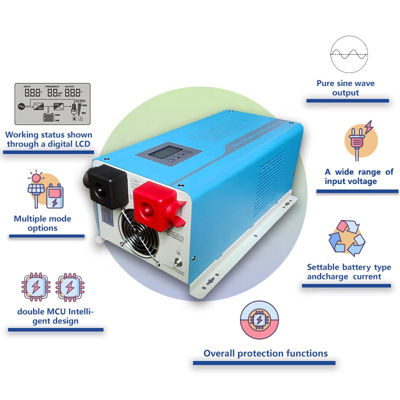
1KW-8KW Power Inverter
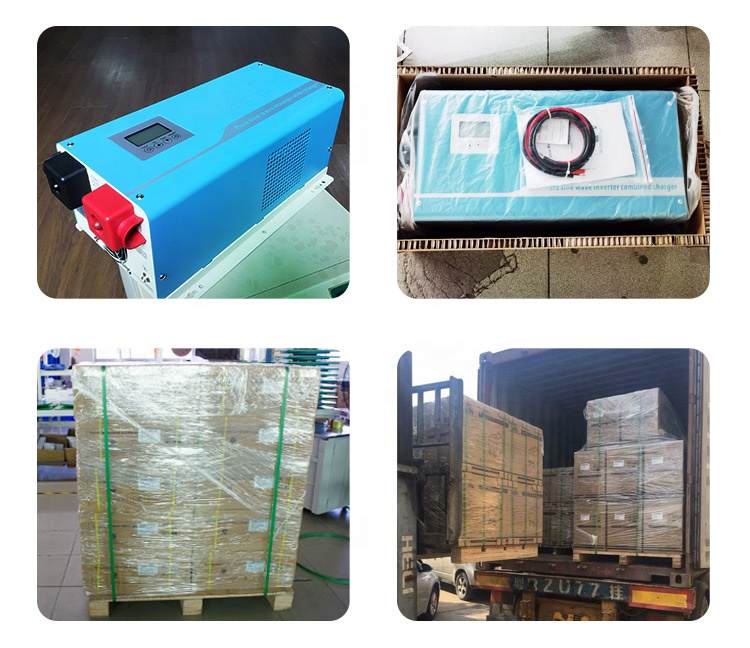
Use double MCU design,the product provides different charge voltages and charge currents to realize charge management for batteries of different types.Its mains supply preferred mode,energy--saving mode and battery preferred mode are all settable,thus making it easy to meet users' different application needs.It has an LCD to show operation status.It is widely applied to families,schools,streets,frontier defense,pasturing areas,industrial equipment,military vehicle--borne equipment,ambulances,police cars,ships,ect.


Nkm Hybrid Inverter With Mppt Charge,Inverter Power Inverter,Hybrid Inverter Charger,Hybrid Grid Tie Inverter
suzhou whaylan new energy technology co., ltd , https://www.xinlingvideo.com