The EMI current probe is a card-type current sensor designed to measure the interference current on the measuring line (single/multiple cable bundles, ground/belt harness, shielded outer conductor and coaxial cable). It is only necessary to clamp it on the line to be tested without the need to make conductive contact with the source wire under test, and to change its circuit. Interference measurement of such a complicated conductive system/electronic circuit or the like can be performed without disturbing its normal operation or normal arrangement. When the probe is clamped to the line to be measured, the conductor under test acts as the primary of the transformer and the secondary is included in the current probe. The current probe (secondary) is designed as a test instrument that can be directly connected to a 50Q system, such as a receiver/spectrum analyzer. The additional shield structure of the current probe measures asymmetric (common mode) interference current or symmetrical (differential mode) interference current.
Current probes vary in frequency from 25 Hz to 1 000 MHz, continuous wave currents from a few amps to tens of amps, and pulse currents from tens of amps to hundreds of amps.
In actual EMI testing, it is necessary to convert the interference voltage received by the receiver to the line under test to test the interference current on the line. Therefore, the calibration of the current probe accurately calibrates the conversion factor of the probe, which is a necessary condition for ensuring the accuracy of the test.
We need to study the calibration method of EMI current probes to find out how to accurately determine the current probes in these applications and prove their effectiveness to ensure the quality of EMI test results.
2 Calibration method
Through the study of GB/T6113-1995 Radio Interference and Immunity Measurement Equipment Specification, combined with the state of the existing equipment in the laboratory, the current probe calibration method was studied.
2.1 Probe calibration principle
Calibration of the current probe requires a fixture consisting of two half-turn coaxial converters. When the current probe is assembled on it, a coaxial line is formed: the current probe is wrapped
For the outer conductor, the inner conductor passes through the diameter of the probe.
Calibration test connection and calibration circuit as shown in Figure 1 and Figure 2
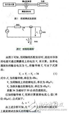
2.2 Configuration and implementation of calibration instruments
According to Figure 1 and formula (1), we consider that two instrument configuration schemes can be used. One is the signal source receiver scheme: the signal received at the receiver and the output voltage of the signal source (logarithmic unit) are measured at the point frequency, and the generation formula (1) is calculated to obtain the transmission guide at each frequency point. The value of yI. The advantage of this method is that it is intuitive and simple, but it needs to be tested at many frequency points when it is used as a calibration curve for the transmission admittance of a certain probe. It is time-consuming, laborious and extremely inefficient.
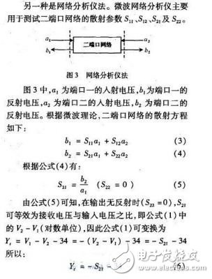
Therefore, the test method is as follows: use the network analyzer to connect the source end to the input end of the calibration rack (port 1) according to Figure 1, the output end of the calibration rack is connected to the matching load, and the current probe output is connected to the input of the network analyzer (end I21) Test the s:, as a function of frequency, by sweeping. Then the curve is corrected according to formula (6) to obtain the transmission admittance frequency curve. The advantage of this method is that the sweep frequency measurement test speed is fast, and the network analyzer can set a curve of 201 points and 9 scans at a time.
3 Calibration procedure and calibration results We repeated the experiment using Method 1 and Method 2 to prove that the test results of the two methods are the same. Focus on the second method, using the laboratory's existing network analyzer 8751A and graphics acquisition software Soft-plotV6.0 to summarize the method steps are as follows:
(1) Insert the USB-GPIB interface card into the PC, load the SoftplotV6.0 drawing software into the PC, and connect the Pc and the network analyzer;
(2) Connect the network analyzer and the cable and adapter needed to calibrate the current probe, and perform straight-through calibration on the network analyzer according to the frequency range of the probe calibration;
(3) Connect the source of the network analyzer to the input of the calibration frame. The output of the calibration frame is connected to the matching load. The output of the current probe is connected to the input (receiver) of the network analyzer, and S: is tested. curve;
(4) Use the drawing software to put S. The curve is taken to the PC;
(5) List the composition S by the list method. 201 data points of the curve;
(6) Copy 201 data into the Excel table in the PC, take the absolute value of the data and subtract 34 (correction coefficient) from the value;
(7) Copy the data in the corrected Excel table to the data table of the drawing software, and draw the corrected curve, which is the transmission admittance-frequency curve;
(8) Copy the transmission admittance curve to the drawing board of the PC, use the u disk to test out or use the printer to check the table when used by the EMI tester.
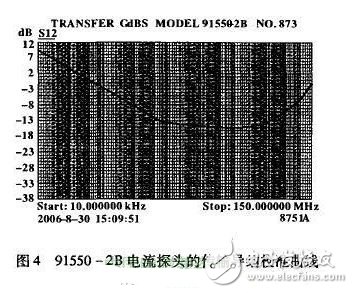
For example, the transmission admittance calibration curve of the 91550-2B current probe is shown in Figure 4.
The EMI current probe calibration method has undergone theoretical analysis and experimental verification. The proposed method and implementation of this method have a positive effect on the improvement of EMI detection quality.
IT System Isolated Power Distribution
It System Isolated Power Distribution,Medical It Isolated Power System,Industrial It Isolated Power System,Healthcare Insulation Monitor
Jiangsu Acrel Electrical Manufacturing Co., LTD. , https://www.acrel-factory.com