Automakers use more cameras and sensors to achieve automotive safety requirements, while Coaxial Cable Power (PoC) provides automotive designers with a compact solution to reduce body weight. However, there is nothing perfect in the world that can cause problems when delivering power and front and rear channel signals over the same cable. In addition, the on-board battery used to power the system produces a wide voltage offset as low as 3V during cold-start operation and up to 42V under clamp load dump or other transient conditions. In order to ensure that important systems such as the Advanced Driver Assistance System (ADAS) can operate in any car condition, a well-designed power supply is essential.
Figure 1 is an example of an ADAS system equipped with a widely used flat panel display (FPD) link III digital video interface. The deserializer transmits and controls signals over the coaxial cable, and the serializer sends back the video signal over the same cable. The system has four significant power modules: the deserializer power supply, the camera power supply on the deserializer side, the serializer power supply, and the camera image sensor power supply.
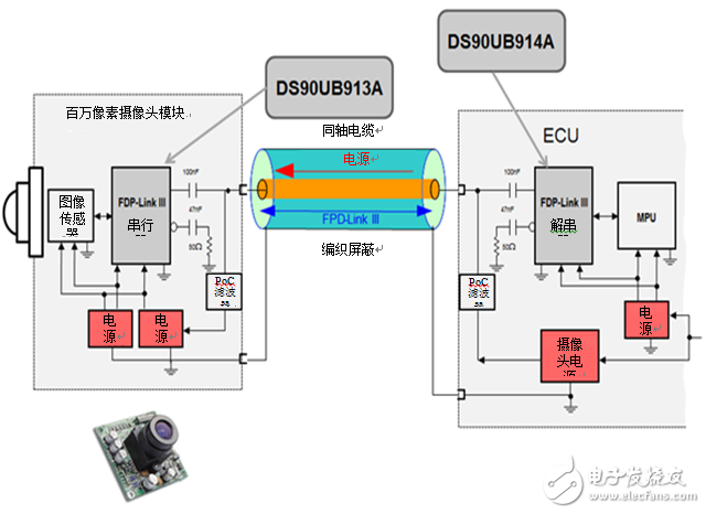
Figure 1: Block diagram of the megapixel camera system module
The biggest challenge of the megapixel camera system is the potential voltage drop of the coaxial cable. To avoid signal integrity issues due to voltage drops, the deserializer voltage must be increased to at least 9V before transmitting the PoC. Once power is delivered to the serializer side, the voltage must be adjusted back to the required operating voltage of the serializer and image sensor.
We take a look at these module diagrams. Starting from the serializer side, size is a major consideration (and noise and power supply rejection ratio [PSRR]), I recommend using the LM53600-Q1 buck regulator, as well as for serializer power and image sensor power supplies. LP5912-Q1 Low Dropout Linear Regulator (LDO). The LM53600-Q1 features a wide input voltage range of 3.55V - 36V, a transient voltage of up to 42V, 23μA quiescent current (IQ) and 3mm &TImes; 3mm package size. It is also recommended that you use the LP5912-Q1 with a power supply rejection ratio of up to 75dB at 1 kHz, an output noise of 12μVRMS, a quiescent current of 30μA, and a package size of 2mm &TImes; 2mm. Because power supply ripple and noise directly affect image quality, high power supply rejection ratios and low output noise are critical for camera applications. Both devices operate with very few external components, thereby enabling miniaturization of the overall solution size.
On the deserializer side, the deserializer power module is similar to the serializer power module. I also recommend using the LM53600-Q1 and LP5912-Q1 to reduce bill of materials (BOM) costs. In this case, you don't have to start with the size to save costs, you can use other solutions. However, these solutions may require the use of more external components, which increases overall design costs. To avoid using additional components, you can visit TI.com.cn to see other solutions that might be right for your design.
Finally, the camera power module delivers power from the deserializer to the serializer over a coaxial cable. The power from this module must be boosted to 9V and matched with the signal path. According to Section 8.5 of the DS90UB91x datasheet, the differential output voltage |VOD| (DOUT+ and DOUT-) is only between 269mV and 412mV. This means that the output of the module must be clean enough to avoid signal-to-noise ratio (SNR) degradation. Fortunately, the PoC filter (used to ensure serializer and deserializer 50? impedance matching) includes an inductor that helps block high frequency ripple from the boost converter. The higher the switching frequency, the greater the attenuation. For this application, I recommend a boost adjustment with a TPS61093-Q1 with a 1.2MHz switching frequency. As shown in Figure 2, after installing an inductor with a typical value of about 100μH in the PoC filter, the output ripple is attenuated by about -57dB, or 0.2% of the original ripple voltage from the boost converter.
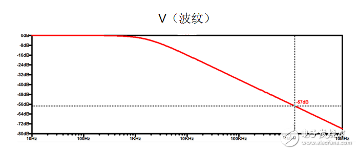
Figure 2: Ripple attenuation produced by a PoC inductor
The megapixel camera has become one of the indispensable sensors in the automotive industry. As cars are used more and more sensors for safety and comfort, the use of well-designed systems for coaxial power transmission saves cost and space.
Welcome to explore TI's broad portfolio of automotive certified components.
Electronic Lock Motor product introduction:
Electronic Lock Motor, also known as Intelligent lock motor, Belong to small reducer series, the main structure composed of drive motor (motor) with a reduction gear box, composed of a shaft connection, form integrated motor reducer; Drive motor is purchasing product, reduction gear box is customized according to the project product demand, the maximum power under 10 w, maximum voltage up to 12 v, below 25 mm diameter size.
Functions: it is widely used in various intelligent locks, such as Shared bicycle lock, fingerprint lock, glass lock, safe lock, hotel lock, family lock, inductive smart lock, etc
Features:China Electronic Lock Motor is based on micro precision reducer development, small intelligent micro precision reducer can do 10 mm in diameter, is widely used in safe, locks, smart locks, sensor intelligent lock;
This kind of motor has the characteristics of low noise, low energy consumption, small volume, light quality, high precision, large torque and durability
Method of use: the best stable in horizontal plane, installed on the China Electronic Lock Motor output shaft parts, cannot use a hammer to knock, knock prone to press into the dc Electronic Lock Motor drive, may cause damage to internal components, and cannot be used in the case of blocked.

Operating temperature range:
Electronic Lock Motor should be used at a temperature of -10~60℃.
The figures stated in the catalog specifications are based on use at ordinary room temperature catalog specifications re based on use at ordinary room temperature (approximately20~25℃.
If a electronic Lock Motor is used outside the prescribed temperature range,the grease on the gearhead area will become unable to function normally and the motor will become unable to start.Depending on the temperature conditions ,it may be possible to deal with them by changing the grease of the motor's parts.Please feel free to consult with us about this.
Storage temperature range:
China Electronic Lock Motor should be stored ta a temperature of -15~65℃.
In case of storage outside this range,the grease on the gearhead area will become unable to function normally and the motor will become unable to start.
Service life:
The longevity of Electronic Lock Motor is greatly affected by the load conditions , the mode of operation,the environment of use ,etc.Therefore,it is necessary to check the conditions under which the product will actually be used .The following conditions will have a negative effect on longevity.Please consult with us should any of them apply.
â—Use with a load that exceeds the rated torque
â—Frequent starting
â—Momentary reversals of turning direction
â—Impact loads
â—Long-term continuous operation
â—Forced turning using the output shaft
â—Use in which the permitted overhang load or the permitted thrust load is exceeded
â—A pulse drive ,e.g.,a short break,counter electromotive force,PWM control
â—Use of a voltage that is nonstandard as regards the rated voltage
â—Use outside the prescribed temperature or relative-humidity range,or in a special environment.
â—Please consult with us about these or any other conditions of use that may apply,so that we can be sure that you select the most appropriate model.
when it come to volume production,we're a major player as well .each month,we rurn out 600000 units,all of which are compliant with the rohs directive.Have any questions or special needed, please contact us, we have the engineer group and best sales department to service to you
Looking forward to your inquiry. Welcome to our factory.

Electronic Lock Motor,Motor For Electronic Lock,Electronic Lock Dc Motor,Electronic Lock High Speed Motor
Shenzhen Shunchang Motor Co., LTD. , https://www.scgearmotor.com