1. Introduction
The rapid advancement of wireless communication systems has driven the need for high-performance, broadband antennas capable of supporting high data rate transmissions. Among various frequency bands, the millimeter-wave band has emerged as a key candidate for short-range, high-speed wireless applications. In response to this demand, researchers have increasingly focused on developing compact and high-efficiency ultra-wideband antennas operating in the millimeter-wave range. Another significant trend in antenna design is the integration of RF front-end circuits with the antenna itself. Traditionally, low-temperature co-fired ceramic (LTCC) has been widely used in RF front-end modules. However, LTCC’s high dielectric constant limits its effectiveness due to narrow bandwidth and strong surface wave propagation. Recently, liquid crystal polymer (LCP) has gained attention as a promising material for RF circuit integration. LCP offers lower loss, flexibility, and excellent moisture resistance, making it ideal for millimeter-wave devices. With a low loss tangent of 0.002–0.004 at 60 GHz, LCP provides a strong foundation for high-frequency applications.2. Ultra-Wideband Slot Antenna Design
2.1 Structural Design of Single-Slot Antenna
Tapered slot antennas are well-known for their wideband operation and high gain. In traditional designs, the ground plane is not utilized, allowing energy to radiate from both sides of the slot. However, when integrating an antenna onto a metal substrate, the presence of the metal can significantly degrade performance, such as reducing the operational bandwidth. Thus, designing a tapered slot antenna with a grounded structure presents both a challenge and an opportunity. Figure 1 shows the cross-sectional view of the LCP-based multilayer structure. The board consists of 8 metal layers and 7 dielectric layers, with a dielectric constant of 2.9. The thickness of the dielectric layers is h1 = 50 μm and h2 = 18 μm. This configuration allows for a more controlled electromagnetic field distribution.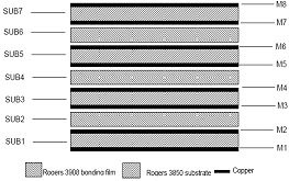
Figure 1: LCP Process Structure
We designed an ultra-wideband slot antenna using a multi-layer LCP board, suitable for millimeter-wave applications. The three-dimensional structure is shown in Figure 2. Energy is fed through a microstrip line on the top layer, and the linear tapered slot is placed on the third metal layer. A microstrip-slot transition couples the signal from the feed line to the radiating slot. Since the third metal layer acts as a ground plane, a via connects the slot to the ground. The second, fourth, fifth, sixth, and seventh layers are partially etched to form air gaps, enhancing mechanical strength and increasing the dielectric thickness to broaden the bandwidth.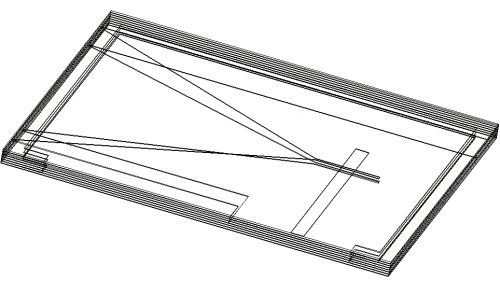
Figure 2: Three-Dimensional Structure
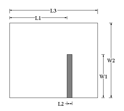
Figure 3: First Layer Microstrip Line
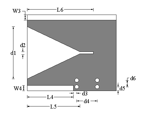
Figure 4: Third Layer Radiation Slot
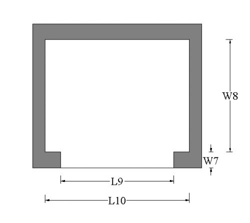
Figure 5: Air Gaps in Layers 2, 4, 5, 6, and 7
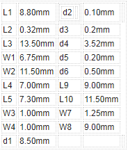
Table 1: Size of Single-Layer Tapered Groove
2.1.2 Simulation Results of the Antenna
The single-layer tapered slot antenna was simulated using Ansoft HFSS and CST software. As shown in Figure 6, the return loss is below -10 dB between 40 GHz and 52 GHz. The gains at 42 GHz and 47 GHz are 2.1 dBi and 3.0 dBi, respectively. However, these results fall short of the required performance for real-world applications.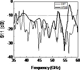
Figure 6: S11 Diagram of Single-Layer Tapered Groove
2.2 Structural Design of Double-Slot Antenna
To further enhance the bandwidth, we introduced a dual-tapered slot design by adding a second tapered groove on the fifth metal layer. The dimensions of the new slot are provided in Table 2. This approach significantly improves the overall bandwidth and radiation efficiency.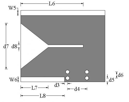
Figure 7: Fifth Layer Tapered Groove
Table 2: Size of Fifth-Layer Tapered Groove
2.2.2 Simulation Results of the Antenna
The double-layer tapered slot antenna was also simulated using HFSS and CST. As seen in Figure 8, the reflection coefficient remains below -10 dB from 33 GHz to 60 GHz, covering the entire low-band millimeter-wave spectrum. The gains at 39 GHz, 42.6 GHz, and 52.7 GHz are 2.1 dBi, 3.0 dBi, and 3.2 dBi, respectively. The radiation pattern at different frequencies is shown in Figure 9.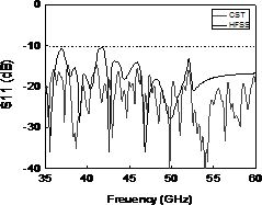
Figure 8: S11 Diagram of Double-Layer Tapered Groove
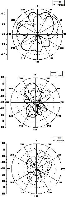
(a) f = 39 GHz (b) f = 42.6 GHz (c) f = 52.7 GHz
Figure 9: Antenna Pattern (φ=0°)
As illustrated in Figure 9, the antenna exhibits multi-band characteristics, with resonance points primarily determined by the length of the tapered slot. Longer slots shift the resonance to lower frequencies, while the opening angle affects the return loss. The radiation pattern remains stable across the operating frequency range, showing consistent directivity and beam pointing. This stability makes the antenna suitable for various applications in complex environments.
3. Conclusion
Based on the LCP process, this paper presents a millimeter-wave ultra-wideband tapered slot antenna. To improve the bandwidth, a dual-tapered slot design was introduced, which effectively broadens the operational range. The grounded structure suppresses backward radiation, ensuring efficient forward transmission. The antenna operates from 33 GHz to 60 GHz with consistent radiation patterns throughout the bandwidth. Its elliptical polarization makes it adaptable to challenging environments. The study demonstrates that LCP technology is highly suitable for developing cost-effective, lightweight, and high-performance millimeter-wave antennas.5-50kg Transport drones,A large payload unmanned aerial vehicle that can be used for multiple purposes and functions such as rescue, transportation, lighting, law enforcement, etc
We can customize drones with different distances, weights, and application scenarios according to customer needs, hoping to bring higher efficiency to your work. Please do not use them for warfare


Customized Throwing Transport Drones,Heavy Duty Drone,Firefighting and Rescue Heavy Drones
Jiangsu Yunbo Intelligent Technology Co., Ltd , https://www.fmodel-ai.com