The reset source is the source of the internal reset operation of the microcontroller, which can be roughly divided into seven types: power-on reset (POR), manual reset (MRST), power under-voltage reset (LVR), watchdog reset (WDR), software reset ( SWR), software and hardware reset (SHR), and illegal address reset (IAR).
1. Power-on reset circuit
The essence of power-on reset is the power-on delay reset, that is, to lock the CPU in the reset state during the power-on delay, to compensate for the time that the power supply of the single-chip microcomputer gradually rises from low to high due to the existence of the power filter capacitor. The following figure shows a common power-on reset circuit formed by the charging time of the RC branch.
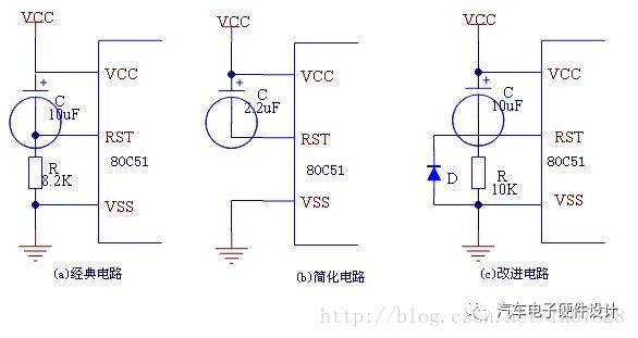
After each single-chip power-off, the charge on the delay capacitor C should be discharged immediately, so that the delay preparation can be made again, and preparation for the possibility of re-energizing the surface in a short time. Otherwise, if the C is not fully discharged after the power is turned off, if the power is turned on again soon, the RC branch will lose its due delay function, and a diode is added to the circuit, as shown in Figure C. Show.
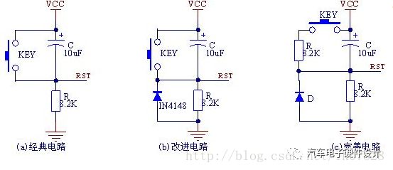
2. Manual reset circuit
In a single-chip microcomputer system, in some cases, the single-chip microcomputer may fall into chaos or crash due to unexpected factors such as electromagnetic interference. At this time, a manual reset is required to reset the single-chip microcomputer. The following figure is an improved version with manual reset based on power-on reset. Delay reset circuit with reset and delay function.
3. Design of discrete components of undervoltage reset circuit
Under-voltage reset is the power drop reset, that is, the power-down lock reset, that is, before the voltage edge of the microcontroller drops to the point where it can no longer work, the microcontroller is provided with an alarm signal or reset signal in advance, and even locks the microcontroller in the reset state.
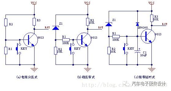
Figure (a) The resistor divider branch is used to set the undervoltage detection threshold voltage value. Normally 9013 is turned on and RST is low. When VCC drops to the threshold voltage VT, RST becomes high. VT=0.7V(R1+R2)/R1.
Figure (b) uses the voltage regulator tube to set the undervoltage detection threshold voltage value. The principle is shown in figure (a). VT=Vz+0.7V.
Figure (c) is an undervoltage reset circuit with a delay function.
4. Design of undervoltage interrupt function
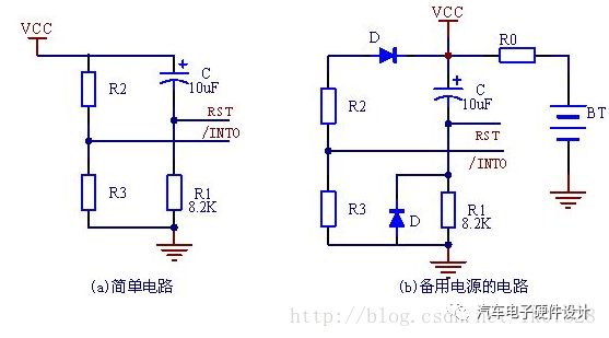
As shown in Figure (a), the voltage divider of R2 and R3 is used to provide an undervoltage interrupt signal for the interrupt pin /INT0, which ensures that /INT0 is usually provided with a logic high level. When the power supply voltage drops or drops to the threshold voltage, Make /INT0 go low.
Figure (b) is the design of the undervoltage interrupt function circuit of a rechargeable battery (or large capacity capacitor) with a backup power supply (3.6V).
5. Voltage detection chip
(1) External voltage detection dedicated chip. Such as the voltage detection and reset circuit built by the HT70XX series produced in Taiwan.
(2) An external voltage detector MAX810x with delay is equivalent to adding a reset delay function on the basis of the HT70XX circuit.
(3) An external voltage detection device MAX812 with manual reset.
(4) An external voltage detector MAX707/708 with power failure warning.
6. Watchdog reset (WDR) and watchdog timer (WDT)
External watchdog dedicated chip DS1232, MAX813
Absolute rotary Encoder measure actual position by generating unique digital codes or bits (instead of pulses) that represent the encoder`s actual position. Single turn absolute encoders output codes that are repeated every full revolution and do not output data to indicate how many revolutions have been made. Multi-turn absolute encoders output a unique code for each shaft position through every rotation, up to 4096 revolutions. Unlike incremental encoders, absolute encoders will retain correct position even if power fails without homing at startup.
Absolute Encoder,Through Hollow Encoder,Absolute Encoder 13 Bit,14 Bit Optical Rotary Encoder
Jilin Lander Intelligent Technology Co., Ltd , https://www.jilinlandermotor.com