In the past ten years, model-based development methods in the field of vehicle electrical and electronic architecture development have been widely accepted, and even as the preferred development method, it has become a necessary measure to ensure the success of the design. With the gradual strengthening of fuel economy, environmental protection and road safety requirements, the overall optimization of the system must be considered in the design of automotive electrical and electronic architecture, and the development efficiency and development time need to be improved. At this time, the model-based method becomes very important. . This method must be implemented with the help of tools. PREEvision is a system architecture design and optimization tool commonly used in OEMs. Its capabilities include requirements development, logic functional design, network and component architecture, electrical system and harness design, and topology design. The tool covers the conceptual prototyping phase to the detailed detailed design phase and supports detailed development and system specification development for large engineering teams. This paper introduces the model-based vehicle electrical and electronic architecture design based on this tool.
Development Process
In order to ensure the quality of the electronic and electrical architecture system, the development of electrical and electronic architecture needs to be developed according to a certain process. The development process of the electrical and electronic architecture mainly includes: determining the market positioning of the vehicle, benchmarking analysis, demand development, architecture model design, and output design file. Wait for steps.
1) Market positioning
The market planning department or the vehicle strategy department analyzes the market performance of the models to be developed through market research, investigates the demand of the sales people, and determines the positioning, shape, style, pre-sale area of ​​the model to be developed according to the current market conditions and the evaluation of the future market. Market prospects and other content. The positioning of the vehicle at this time determines the complexity of the subsequent models and the development of electronic and electrical systems.
2) benchmark analysis
Before developing a new model, it is generally necessary to select one or several existing models within the company and competitor models with better market performance for comprehensive benchmark analysis to obtain the relevant functional and non-functional characteristics of the benchmark vehicle. The benchmark analysis includes the following contents: electronic and electrical characteristics configuration; functional requirements specification; vehicle driving and operation measurement; CAN bus measurement; power supply system analysis; electronic and electrical topology analysis; ECU node technical specification analysis; electronic and electrical cost analysis.
When the benchmarking workload is large, the benchmarking results contain a lot of information. Generally, the document is not stored in the form of documents, but the benchmark data is saved in the enterprise database, such as the electronic and electrical system database provided by PREEvision. The results of the benchmark analysis can be used to analyze the deficiencies of existing models, propose new functional requirements and provide blueprints and materials for the design of new models.
3) Demand development
The work of demand development needs to be combined with the market positioning and benchmarking results of the model, and combined with the relevant data of the previous models. It mainly includes two aspects: determining the requirements specification and formulating the evaluation criteria.
To determine the requirements specification, we first need to collect the customer's requirements and the requirements of laws and regulations, and initially determine the overall functional requirements. Secondly, we can collect reference information for other models. If it is a retrofit project, we can refer to the demand documents of existing models. If it is a new model, Refer to the demand information of the benchmark vehicle; again, the customer requirements and regulatory requirements need to be specified, and the technical language description should be used to formulate specific technical requirements documents to form an Excel list or a DOORS file.
The evaluation criteria are jointly formulated by experts in relevant fields within the company. The development of evaluation criteria is divided into two aspects. One is to determine the various factors that need to be considered when evaluating the model, and the other is to determine the weight of each influencing factor. After the electronic and electrical architecture modeling is completed, model evaluation and variant comparison are performed according to the evaluation criteria. Figure 1 shows an example of the criteria for judging.
This article refers to the address: http://
4) Electronic and electrical architecture model design
In the development process of the vehicle electrical and electronic system, it will involve various aspects such as requirements, function design, network design, function distribution, and harness design, which will be jointly developed by different departments or engineering teams. In order to achieve a reasonable division of labor and collaboration in the multi-team parallel development process, the entire electrical and electronic architecture design needs to be developed according to the idea of ​​layered design (as shown in Figure 2). In the process of model development, continuous evaluation and optimization is required, and finally the optimal design is selected.

a) Requirements definition
This layer needs to import the work of demand development - the requirements specification, or directly carry out the work of demand development at this stage. This layer is used to describe the functional and non-functional requirements of the electronic and electrical system, and is the starting point for the design of electronic and electrical architecture.
b) Functional logic design
This layer defines the logical implementation of the entire system function. The functional network layer includes functional modules such as logic sensors, function blocks, and logic actuators, as well as information interaction interfaces between the functional modules. When the ports between the modules of the functional network layer are connected through the information interaction interface, the corresponding module can exchange data and control information. In the functional network, the user can see the logical relationship between the functional modules.
c) hardware system design
This layer mainly includes a network layer, a component layer, and a principle layer. The network layer describes the logical connections between the components, such as bus systems, traditional connections, power supplies, and ground connections, which are further refined in the subsequent line principle layer; the component layer describes the internal components of each component. And the detailed information of its external interface; the line principle layer describes the specific implementation of the logical connection in the network layer, such as the specific wire, cable connection, internal structure of the insurance relay box.
d) harness layer design
The logical and principle connection is physically implemented in the wire layer. In this layer, the connection relationship of the line principle layer can be further refined in both the wire and the cable, and the wire bundle specific attributes are added to the model. Each wire (or cable) and corresponding connector in the layer has its physical properties (including information on unit length weight, cost, overcurrent capability, etc.). Wire harness elements can later form specific wire and cable layouts in the topology (including the placement of the bond points and mating plugs, etc.).
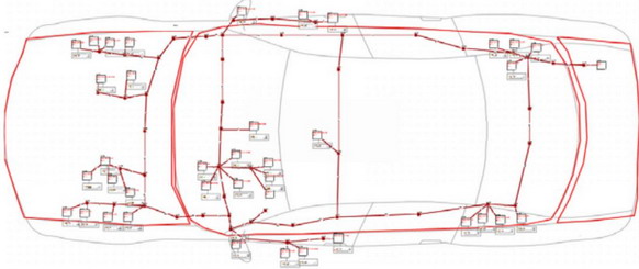
e) Topological layer design
This layer describes the actual layout of the electrical and electronic system. The designer needs to determine the final installation position of each component and the harness according to the actual situation. It is necessary to set the specific length of the "line segment" between different installation positions. The statistical length of the entire harness in the electrical and electronic system can then be derived.
5) Output design file
After determining the optimal solution, the design specifications of the entire system, subsystems, and components can be output according to this scheme. Distribute the specification to relevant departments for specific design.
Model application and advantages
The electronic and electrical architecture model developed through layering is a system with rich attributes, which can be used for a variety of applications. The model-based development method brings many advantages to the development of vehicle electrical and electronic.
1) Unified development tools
In the development of traditional electronic and electrical architectures, relying on tools such as Excel, Visio, and Word, a large number of documents are generated. The model-based development approach uses a unified development tool to integrate the relevant content of the electrical and electronic system into a single tool, thus forming an overall database to ensure data consistency.
2) Data tracking function
The PREEvision tool uses a layered development approach to build a model of the electrical and electronic architecture. The mapping between the layers is achieved through more than 30 information mapping methods across different technical levels, making the electrical and electronic architecture model a whole, ensuring the entire model. Consistency, data tracking at the same time, rapid synchronization of design changes and rapid location of error sources.
3) Consistency check
The model-based approach enables rapid consistency checks to verify the integrity and inconsistency of the entire structure; it can verify that the model meets the overall requirements and custom requirements. Inconsistent elements can be quickly retrieved under the support of tools, making the resolution of related problems easier.
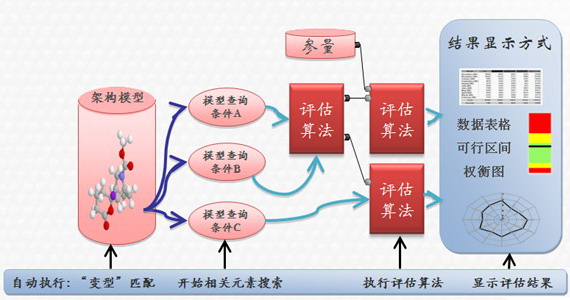
4) Architecture assessment
In addition to meeting functional requirements, the system architecture should be as specific as possible to meet specific performance requirements. The model-based approach enables evaluation of various parameters in the electrical and electronic model based on specified evaluation algorithms and computing environments. Through the framework evaluation, the estimated value of the metric can be obtained or even the accurate result, and then the result can be quantitatively evaluated according to the predetermined reference value.
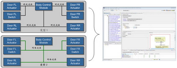
5) Variant management
In the process of architecture development, multiple schemes are designed at the same time, and the method for comparison and selection is called “variantâ€. Model-based development can easily decompose the overall model into multiple model components, and can create multiple alternatives for model components and re-integrate them. The function of the architecture evaluation can effectively evaluate the advantages and disadvantages of various solutions and obtain a reliable electronic and electrical system architecture model.
In addition, the model-based development method can integrate the electronic system and electrical system of the vehicle well, and can optimize the electronic and electrical of the whole vehicle globally; the electronic and electrical model is very easy to reuse, which is beneficial to the company's technology accumulation.
Summary of this article
The development process of the model-based electronic and electrical architecture development method is generally: determining the vehicle market positioning, vehicle benchmarking analysis, demand development, architecture model design, output scheme design documents and other steps. The model-based development method can adopt a unified tool to ensure the consistency of the model data, facilitate the convenient variant management, and provide fast and automatic evaluation calculations, making the development of the electrical and electronic architecture of the OEM more rapid. Convenient.
Motion control sensor is an original part that converts the change of non-electricity (such as speed, pressure) into electric quantity. According to the converted non-electricity, it can be divided into pressure sensor, speed sensor, temperature sensor, etc. It is a measurement, control instrument and Parts and accessories of equipment.
Remote Control Motion Sensor,Photocell And Motion Sensor,Homeseer Motion Sensor,Lutron Motion Sensor Caseta
Changchun Guangxing Sensing Technology Co.LTD , https://www.gx-encoder.com