First, STM32 general timer principle                        Â
The STM32 series of CPUs has up to eight timers. TIM1 and TIM8 are advanced timers that can generate three pairs of PWM complementary outputs. They are commonly used for three-phase motor drives. Their clocks are generated by the output of APB2 . The other six are normal timers, and the clock is generated by the output of APB1 .
The following figure is a screenshot of the timer clock section in the clock distribution diagram on the STM32 Reference Manual:
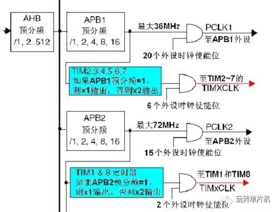
As can be seen from the figure, the clock of the timer is not directly from APB1 or APB2 , but from a frequency multiplier whose input is APB1 or APB2 , the blue part in the figure.
The following uses the general-purpose timer 2 clock to illustrate the role of this multiplier: when the prescaler coefficient of APB1 is 1 , this multiplier does not work, the clock frequency of the timer is equal to the frequency of APB1 ; when the APB1 is pre-divided When the frequency coefficient is other values ( ie, the prescaler is 2 , 4 , 8, or 16) , the multiplier functions, and the clock frequency of the timer is equal to twice the frequency of APB1 .
There may be some students who still don't understand it. OK , let's take an example. Assume that AHB=36MHz , because the maximum frequency allowed by APB1 is 36MHz , so the prescaler coefficient of APB1 can take any value;
When the prescaler coefficient = 1 , APB1 = 36MHz , the clock frequency of TIM2~7 = 36MHz (the frequency multiplier does not work ) ;
When the prescaler coefficient = 2 , APB1 = 18MHz , under the action of the frequency multiplier, the clock frequency of TIM2~7 = 36MHz .
Some people may ask, since the clock frequency of TIM2~7 is required to be 36MHz , why not directly take the prescaler coefficient of APB1 =1 ? The answer is: APB1 not only provides clocks for TIM2~7 , but also clocks other peripherals; setting this multiplier can ensure that other peripherals use lower clock frequencies.
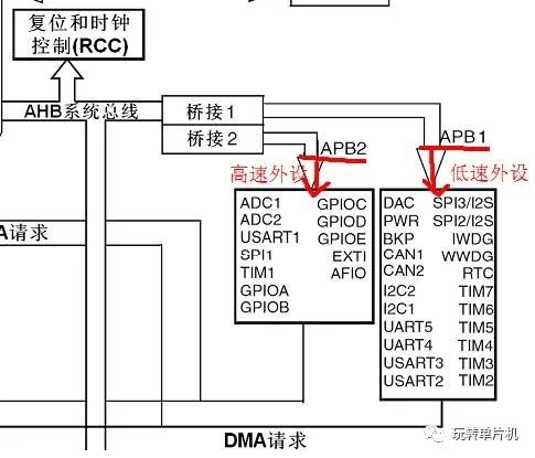
Stm32 peripheral user manual, as shown:
Another example: when AHB = 72MHz, APB1 the prescaler must be greater than 2, since the maximum frequency is APB1 only 36MHz. If the prescaler coefficient of APB1 is 2 , then because of this frequency multiplier, TIM2~7 can still get the clock frequency of 72MHz . The ability to use a higher clock frequency undoubtedly increases the resolution of the timer, which is the original intention of designing this frequency multiplier.
Second, STM32 general purpose timer programming
Timer programming is the programming of interrupts. Because the timer must use interrupts.
 Â
Step 1: RCC_Configuration();// Set the system clock, including the configuration of the clock RCC , multiplying to 72MHZ .
     Â
Step 2: GPIO configuration, using the function GPIO_cfg ();, the function is implemented as follows:

In fact, the timer does not need to configure the GPIO pins, but we are in the timer experiment,
Use the LED light to illuminate every second to experiment, so you need to configure the corresponding GPIO pin.
Step 3: Nesting the configuration of the interrupt controller, we still use the function NVIC_Config(); only the initialization process is slightly different. Here we also list the function implementation:
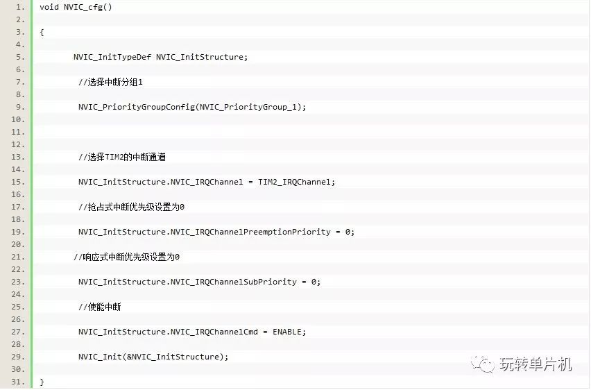
From the above function implementation, the value of the structure member NVIC_IRQChannel is actually changed. The channel required now is the channel of TIM2, so the initialization value is TIM2_IRQChannel. It can also be seen from this that this function can actually be seen as a model, which can be used directly in other programs.
Step 4: Initialize the timer configuration, using Timer_Config(); OK , the key part is out.
Let's look at the implementation process:
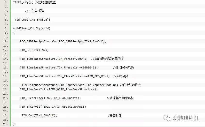
We will explain each statement. First we want to use the timer, we must enable the timer clock, this is the function RCC_APB1PeriphClockCmd ();, through which RCC_APB1Periph_TIM2 is turned on.
TIM_DeInit(TIM2); This function is mainly used to reset the TIM2 timer and put it into the initial state.
Then we assign a value to the auto-reload register. The size of TIM_Period actually means that an update or interrupt will occur after TIM_Period counts. Next, you need to set the clock prescaler number TIM_Prescaler . Here is a formula, for example, to illustrate: clock frequency = 72MHZ / ( clock prescaler +1) . Explain that the currently set TIM_Prescaler directly determines the clock frequency of the timer. It is popular to say how many times a second can count. For example, the calculated clock frequency is 2000 , that is,
It counts 2000 times in one second, and if TIM_Period is set to 4000 , it will be interrupted once after 4000 counts. Since the clock frequency is counted 2000 times in one second, it will be interrupted once as long as 2 seconds.
For further code, there is one more thing to note, TIM_TimeBaseStructure.TIM_CounterMode=TIM_CounterMode_Up; that is, we generally use the up counting mode, that is, increment 1 every time, until the register overflow occurs. Finally, don't forget, you need to enable the timer! !
Interruption time = (TIM_Prescaler+1)* (TIM_Period+1)/FLK
Using the above formula, it can be calculated: the interruption time (2000-1+1)*(36000-1+1)/72000000=1 seconds
Step 5: Write the interrupt service routine. Also need to pay attention to, as soon as you enter the interrupt service routine, the first step is to clear the interrupt flag. Since we are using the overflow mode, we use
The function should be: TIM_ClearITPendingBit(TIM2,TIM_FLAG_Update);
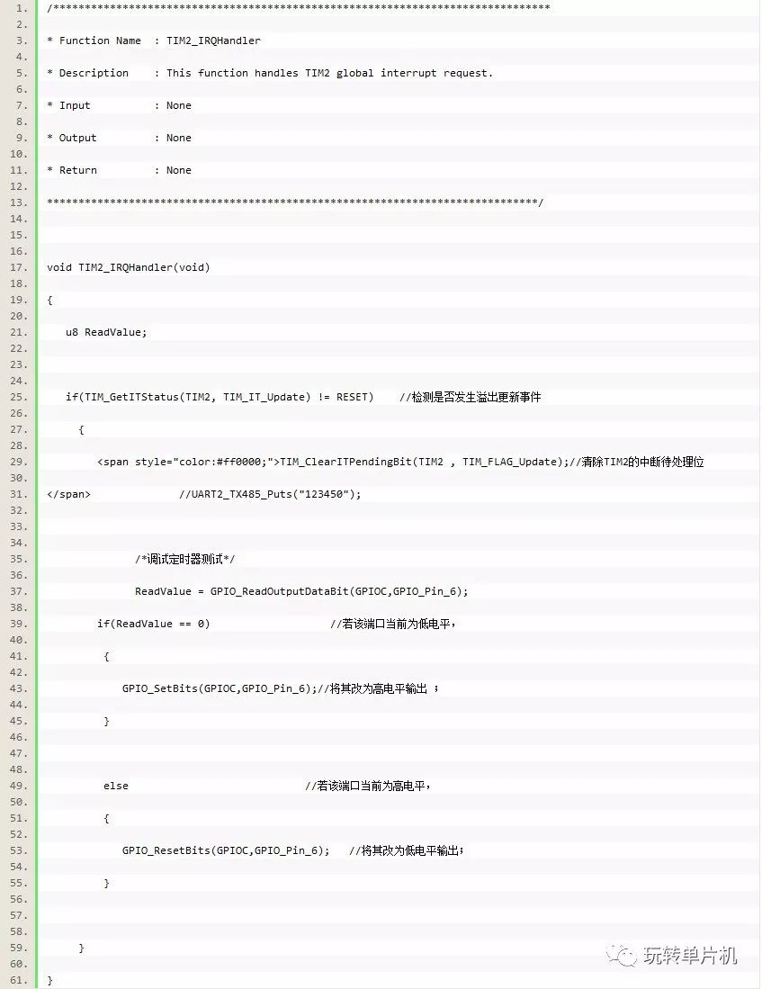
The interrupt service program implemented by the STM32 development board is as follows:
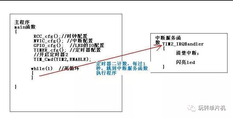
Every second, when an interrupt occurs, enter the interrupt function execution program, let the LED flash , the file where the interrupt program is located stm32f10x_it.c
Ordinary timer working principle diagram
Compile the completed code to download in my resources: http://download.csdn.net/detail/yx_l128125/4508425
Shenzhen ChengRong Technology Co.,Ltd. , https://www.laptopstandsuppliers.com