The servo motor is also called the execution motor, or the control motor. In an automatic control system, a servo motor is an actuator that converts a signal (control voltage or phase) into a mechanical displacement, that is, changes the received electrical signal to a certain rotational speed or angular displacement of the motor. Its capacity is generally 0.1-100W, and commonly used is 30W or less. Servo motors are divided into DC and AC.
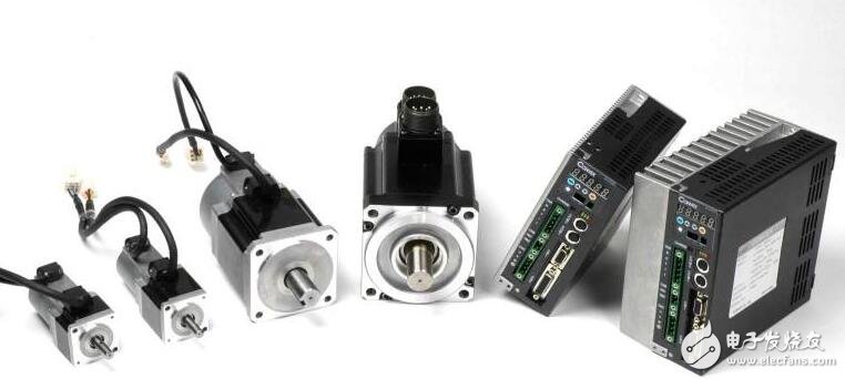
The rotor inside the servo motor is a permanent magnet. The U/V/W three-phase electric motor controlled by the driver forms an electromagnetic field. The rotor rotates under the action of the magnetic field. At the same time, the encoder feedback signal from the motor is supplied to the driver. The driver according to the feedback value and target. The values ​​are compared to adjust the angle at which the rotor rotates. The accuracy of the servo motor is determined by the accuracy (number of lines) of the encoder. The servo motor controls the engine in which the mechanical components operate in the servo system. It is a supplementary motor indirect transmission. Also known as an actuator motor, in an automatic control system, acting as an actuator that converts the received electrical signal into an angular displacement or angular velocity output on the motor shaft. Divided into two major categories of DC and AC servo motors.
Servo motor debugging method1, initialization parameters
Initialize the parameters before wiring.
On the control card: select the control mode; clear the PID parameter; let the default enable signal be turned off when the control card is powered on; save this state to ensure that the control card is in this state when it is powered on again.
On the servo motor: set the control mode; set the enable by external control; the gear ratio of the encoder signal output; set the proportional relationship between the control signal and the motor speed. In general, it is recommended to make the maximum design speed in the servo operation correspond to the 9V control voltage. For example, the mountain is set to 1V voltage corresponding to the speed, the factory value is 500, if you only want to let the motor work below 1000 rpm, then set this parameter to 111.
2, wiring
Power off the control card and connect the signal cable between the control card and the servo. The following lines must be connected: the analog output line of the control card, the enable signal line, and the encoder signal line for the servo output. After reviewing the wiring without errors, the motor and control card (and PC) are powered up. At this point, the motor should not move, and it can be easily rotated with an external force. If not, check the setting and wiring of the enable signal. Rotate the motor with an external force to check whether the control card can correctly detect the change of the motor position, otherwise check the wiring and setting of the encoder signal.
3. Test direction
For a closed-loop control system, if the direction of the feedback signal is incorrect, the consequences must be catastrophic. The servo enable signal is turned on by the control card. This is the servo should be rotated at a lower speed, which is the legendary "zero drift". On the general control card, there will be commands or parameters that suppress zero drift. Use this command or parameter to see if the motor speed and direction can be controlled by this command (parameter). If it is not possible to control, check the parameter settings of the analog wiring and control mode. Confirm that a positive number is given, the motor rotates forward, and the encoder count increases; given a negative number, the motor reverses and the encoder count decreases. Do not use this method if the motor has a load and the stroke is limited. Do not give excessive voltage to the test. It is recommended to be below 1V. If the directions are inconsistent, you can modify the parameters on the control card or motor to make them consistent.
4, suppress zero drift
In the closed-loop control process, the existence of zero drift will have a certain influence on the control effect, and it is best to suppress it. Use the control card or servo to suppress the parameters of zero drift, carefully adjust to make the motor speed approach zero. Since the zero drift itself has a certain randomness, it is not necessary to require the motor speed to be absolutely zero.
5, establish closed-loop control
Once again, the servo enable signal is released by the control card, and a small proportional gain is input on the control card. As for how big the calculation is small, this can only be felt by feeling. If it is not reliable, the minimum allowable input control card is input. value. Turn on the control card and servo enable signals. At this point, the motor should have been able to act roughly in accordance with the motion instructions.
6, adjust the closed loop parameters
Fine-tuning the control parameters to ensure that the motor moves according to the instructions of the control card, this is a must-do work, and this part of the work, more experience, can only be omitted here.
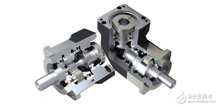
1, the traditional method of selection
Only the dynamics of the motor are considered here. For the linear motion velocity v(t), the acceleration a(t) and the required external force F(t), they can all be expressed as a function of time, independent of other factors. Obviously, the maximum power P motor of the motor should be at most greater than the peak power P peak required by the working load, but this is not enough. The physical power includes both torque and speed, but in the actual transmission mechanism they It is restricted.
The maximum value or peak value is represented by the T peak. The maximum speed of the motor determines the upper limit of the reduction ratio of the reducer. n upper limit = peak value, maximum / peak value. Similarly, the maximum torque of the motor determines the lower limit of the reduction ratio. The lower limit of n = T peak / T motor, the maximum, if the lower limit of n is greater than n upper limit, the selected motor is not suitable. Conversely, a range of possible gear ratios between the upper and lower limits can be determined by a broad analogy for each type of motor. The principle of using only peak power as the motor of choice is not sufficient, and the accurate calculation of the gear ratio is very cumbersome.
2, the new method of selection
A new selection principle is to separate the motor characteristics from the load characteristics and to express them in graphical form. This representation makes the feasibility check of the drive device and the comparison between different systems more convenient. In addition, the gear ratio is also provided. A possible range.
The advantages of this method: suitable for a variety of load conditions; separate the load and motor characteristics; the various parameters of the power can be represented in graphical form and applicable to a variety of motors. Therefore, it is no longer necessary to use a large analogy to check whether the motor can drive a particular load. The gear ratio between the motor and the load changes the dynamic load parameters provided by the motor.
It is more convenient and, in addition, provides a possible range of gear ratios.
The advantages of this method: suitable for a variety of load conditions; separate the load and motor characteristics; the various parameters of the power can be represented in graphical form and applicable to a variety of motors. Therefore, it is no longer necessary to use a large analogy to check whether the motor can drive a particular load. The gear ratio between the motor and the load changes the dynamic load parameters provided by the motor.

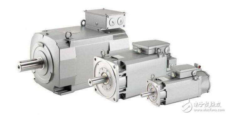
Some servo motor systems are described below, involving permanent magnet synchronous motors and induction asynchronous motors.
A servo system is not just a motor. It is a closed-loop motion system that contains controllers, drivers, electronics, and feedback devices, usually with an optical or magnetic encoder.
The servo system can synchronize the machine with permanent magnets (PM) technology, with a brushed or brushless PM motor, or an asynchronous mechanical system on an AC induction motor.
Permanent magnet synchronous motors have high peaks and constant torque for high acceleration and precision deceleration drive servo systems in precision displacement systems. Torque is directly proportional to the input current. The motor shaft speed is related to the input voltage. The higher the input voltage, the higher the speed of the motor. The curve of the ratio of torque to speed is linear.
The permanent magnet structure is related to the motor air gap. For example, the structure of a brushless PM motor consists of two alternating magnetic structures, the moving rotor (connected to the permanent magnet) and the stator coil generate an electromagnetic reaction, resulting in the torque and speed of the motor.
The three-phase stator field energy sequentially generates energy, and the PM rotor follows the rotor field to complete the synchronous motion. A specific electronic compensation system for checking the rotor position and energizing the stator coils. Brushless PM motors are the first choice for precision displacement systems in all other motors, in addition to automotive applications and very large motor systems. Brushless PM motors are the only servo motor systems that can be used in closed loop torque, speed or displacement systems.
Different rotors
AC induction motors have the same physical characteristics as PM brushless motors
The stator, but its rotor structure is completely different. The squirrel cage induction motor consists of a series of induction aluminum or copper strips placed in the rotor structure and attached to the end coil.
These short rotor bars are electromagnetically coupled to the rotating magnetic field of the stator to create a new rotor field that interacts with the stator field to form rotor motion.
There is a difference between the synchronous stator and the slower stator field and the actual speed. The difference in speed is the so-called slip. The frequency of the input determines the speed of the motor.
For example, a 60 Hz, two-pole AC induction motor with a speed of nearly 3,600 rpm at no load and a four-pole AC motor running at less than 1,800 rpm, depending on the slip difference. When the motor starts torque, the slip increases and the speed decreases.
The AC induction motor will output more torque, and as the speed decreases, until the load reaches the point of failure, the motor speed will drop to zero. An inherent AC motor performance feature is that the initial torque is small and the load must be removed at the start of the motor.
With the advent of inverter electronic drives at the end of the 20th century, the motor-specific torque-speed performance curve has also changed a lot. The performance of the frequency converter is that the voltage and frequency can be changed at the same time, and the torque-speed curve can be reconstructed by using an adjustable or variable speed drive. The AC induction motor is the main link of the speed system.
how to use
Driven technology continues to improve in performance, bringing brushless PM and AC induction motors to the competition in the drive market, but brushless PM motors still dominate the control field. AC induction motors are not suitable for use at low speeds and high speeds.
A brushless PM motor is used in a servo-displacement system, typically with a system of 50 kW (67 hp) or higher. AC induction motors are typically used in constant speed or variable speed systems. Mixed solution systems are relatively rare. Other motors can also be partially implemented, but there are fewer solutions in performance than AC induction motors or brushless PM motors.
In the speed control, the brushless PM motor has a certain impact on the speed control of 1 kW (1.37 hp) DC brushed motor or the application of low power. The AC induction motor controls most applications larger than 1 MW.
Single Phase Ac Motor,Ac Single Pole Motors,Single Phase Motor,Single Phase Motor Connection
Changzhou Sherry International Trading Co., Ltd. , https://www.sherry-motor.com