Circuit Operation Principle The vision health table lamp circuit consists of a power supply circuit, a timing control circuit, an LED indicating circuit, a dimming circuit, a light detection, and an audible and visual alarm circuit, as shown in Figure 9-72.
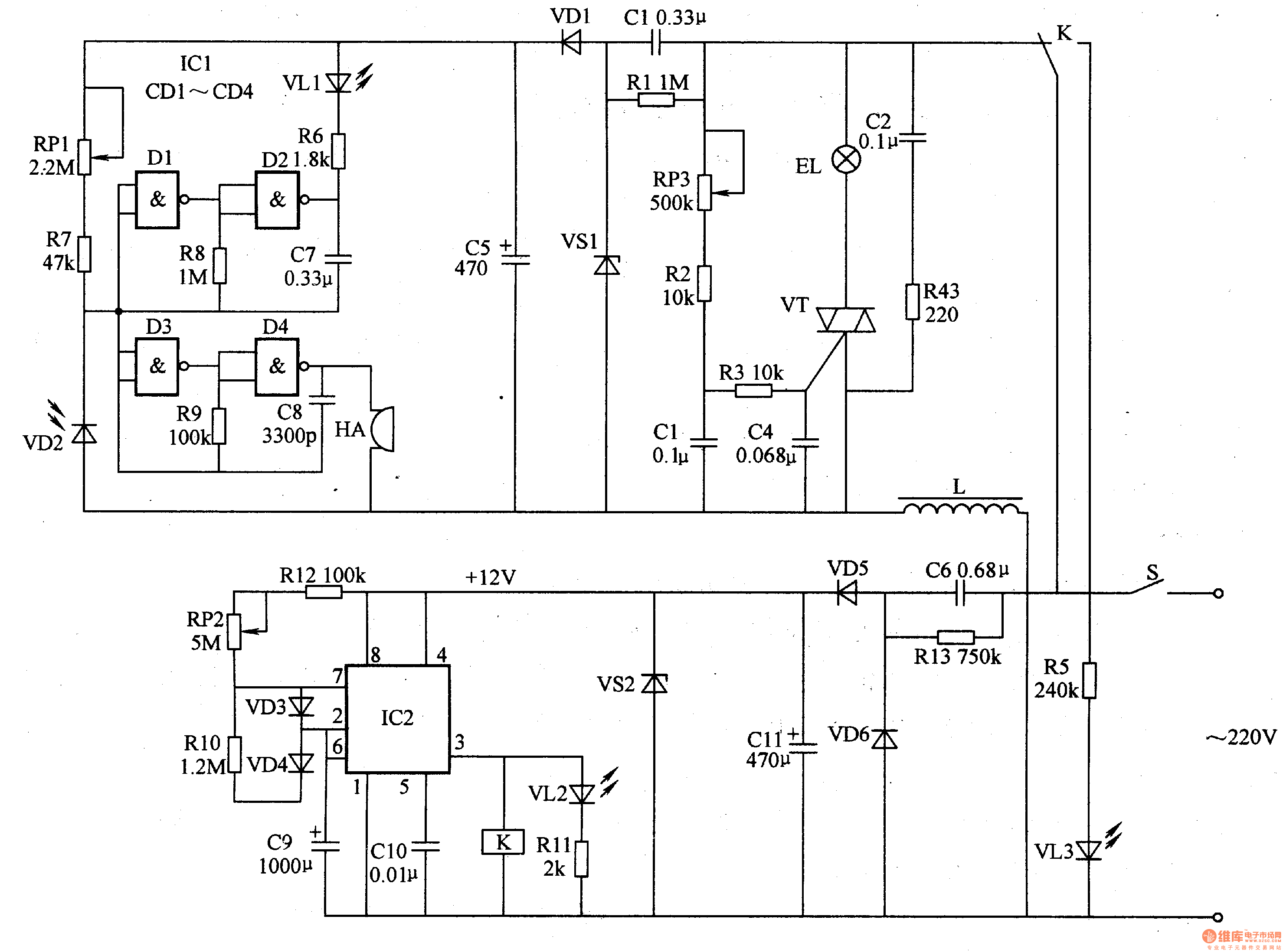
The power circuit is composed of a power switch S, resistors Rl, R13, capacitors Cl, C5, C6, C11, rectifier diodes VD1, VD5, VD6, Zener diodes VS1, VS2 and an inductor L.
The timing control circuit is composed of resistors R10, R12, potentiometer RH, capacitors C9, ClO, diodes VD3, VD4, time base integrated circuit IC2 and relay K.
The photoelectric routing potentiometer RP3, the resistors R1-R4, the capacitor C2-C4, the thyristor VT and the illumination lamp EL are composed.
The LED indicating circuit is composed of resistors R5, R11 and light emitting diodes VL2, VL3.
The light detection circuit is composed of a potentiometer RP1, a resistor R7 and a photodiode VD2.
The sound and light alarm circuit is composed of a NAND gate integrated circuit ICl (Dl-D4), resistors R6, R8, R9, capacitors C7, C8, a light-emitting diode VLl and a buzzer HA. The NAND gates D1, D2 and R8, C7 form a set of oscillators, and the NAND gates D3, D4 and R9, C8 form a set of oscillators.
Turn on the power switch S, the AC 220V voltage is reduced by C6, VD5 and VD6 rectification, Cll filtering and VS2 voltage regulation, and provide +12V working voltage for the timing control circuit.
After the timing control circuit is energized, the 3 pin of IC2 outputs a high level, so that K is energized, VL2 is lit, K's normally open contact is turned on, AC 220V voltage is added to the light control circuit via L, so that VT Turn on, EL lights up; the other way through the Cl step-down, VSl voltage regulation, VDl rectification and C5 filtering, provide the DC voltage around the gV for the light detection circuit and the sound and light alarm circuit. At the same time, C9 is charged via VD3 and RP2, Rl2.
When the voltage across C9 is charged above 8V (about 45min), the circuit in lC2 is turned over, the 3 pin becomes low level, K is released, VL2 is extinguished, the normally open contact of K is disconnected, the illumination lamp EL is extinguished, VL3 point Bright, remind the user to take a break.
While IC3's 3 pin outputs a low level, Cg discharges the circuit in IC7's 7th pin through VD4 and RlO. When the voltage across C9 drops below 4V (about l5min), the circuit inside IC2 flips again, and the 3 pin output High level, K is energized, VT is on, ELA is on.
When the brightness of the light is suitable for reading and writing, the internal resistance of VD2 is stronger and the internal resistance is lower. The two oscillators do not oscillate, VLl does not emit light, and HA does not sound. If the brightness of the light is too low, the internal resistance of VD2 will become larger, so that the two sets of oscillators will oscillate, VLl will flash and HA will sound a warning sound. At this time, VT can be increased by adjusting RP3. The conduction angle increases the brightness of the EL.
Adjusting the resistance of RPl can change the sensitivity of the light detection circuit.
Adjust the resistance of RP2 to change the timing time.
Component selection
Rl-R13 uses 1/4W carbon film resistor or metal film resistor.
Both RPl and RP2 use organic solid potentiometers; RP3 uses synthetic carbon membrane potentiometers.
Cl, C2 and C6 select CBB capacitors with a withstand voltage of 450V; C3, C4, C7 and ClO use monolithic capacitors or polyester capacitors; C5, Cg and Cll select aluminum electrolytic capacitors with a withstand voltage of 16V; C8 is used High frequency ceramic capacitors.
VDl, VD5 and VD6 select 1N4007 type silicon rectifier diode for use; VD2 selects 2CU or 2DU series of photodiode; VD3 and VD4 select 1N4148 type silicon switch diode for use.
VSl selects lW, 9.2-9.6V silicon steady-state diode; VS2 selects lW, l2V silicon steady-state diode.
VLl-VL3 selects p3mm high brightness LED.
L is wound around 50 φ on a φ 5 mm core using an enamel wire of φ 0.68 mm.
VT selects TLC336A type bidirectional thyristor.
ICl selects CD401l or CC4O1l, MCl4011 type four NAND gate integrated circuits; IC2 selects NE555 type time base integrated circuit.
HA uses a piezoelectric buzzer.
The EL uses an incandescent bulb of 40-1OOW.
S selects 5A, 220V power switch.
Genki Ippai 1.0 uses high-tech temperature control, food grade pod and high-quality material device. We also upgrade to type-C interface for charging faster. We have developed various flavors for Genki Ippai Pod Systems. Up to 11 flavors provide consumers with more choices. What's more, you can use other brand`s vape pen with our vape pod.
We offer low price, high quality Disposable E-Cigarette Vape Pen,Electronic Cigarettes Empty Vape Pen, E-cigarette Cartridge,Disposable Vape,E-cigarette Accessories,Disposable Vape Pen,Disposable Pod device,Vape Pods to all over the world.
Pod Systems Vape And Smoke,Vape Pod System Device,Pod System Vape Kit,Pod System Mini Vape Pod
Shenzhen WeiKa Technology Co.,Ltd. , https://www.zgarecigarette.com