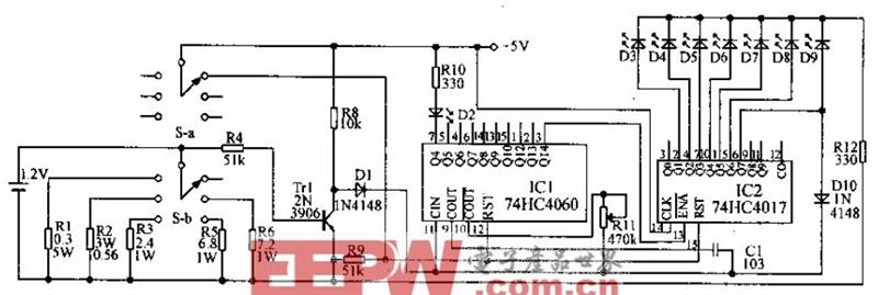
As shown in the figure, the rechargeable battery tester: the longer the rechargeable battery is used, the smaller the capacity and the longer the charging time. This circuit can measure the capacity of a rechargeable battery. When fully charged, the new 9VAAA, AA, C, D electric capacity is 0.1, 0.18, O.5, 2.2, 4A.H. In the circuit, the switch s is used to select the appropriate resistance for one hour. Speed ​​discharges these batteries. The 4060 is a 14-stage binary counter. The internal oscillator frequency is determined by R11 and Cl. Adjusting R11 causes IC1's pin 3 (Q14) to send a pulse to the decimal counter 4017 every 12 minutes, while the 7-pin (Q4) of ICl is illuminated. Diode D2 provides a signal at a frequency of 1.4 Hz and the dipole arm display circuit is operating. The oscillation is controlled by the battery voltage: if it is higher than 0.9V, Tl saturation turns D1 off; if the voltage is low enough to turn off T1, D1 is turned on, and the oscillator stops sending signals to D2. D3-D9 shows the capacity of the electric, between 20% and 140%, the interval is 20%. When D9 is bright, its Q7 drive from 1C2 stops the oscillator through D10, so the battery voltage is at least higher than normal. Before 40%, the D9 is always on.
HQD Vape pen, Wholesale HQD Vape, HQD Manufacture
Shenzhen Xcool Vapor Technology Co.,Ltd , https://www.szxcoolvapor.com