Abstract: With the acceleration of the work rhythm, it is often impossible to pay attention only to the pot that is being burned during cooking, so that problems such as casseroles and burns often occur, and the accidents are often seen. This paper presents an economical and convenient solution by adding certain electronic devices to the inlet end of the lid and the gas stove.
Key words: multi-function; pot lid; anti-dry burning; anti-clay pot
0 Introduction At present, most households use ordinary gas cookers. It is not uncommon for accidents such as fire extinguishing and cooking. When cooking, always stare at it. If you are not careful, you may burn the pot, ignite the fire, or burn it to cause a fire. The safety of the kitchen and the liberation from the care of the cooking meal have become an important issue for every family to consider. Although there are gas stoves with various protection functions on the market, considering the high value, it is unfortunate that the existing gas stoves are thrown away and cannot be replaced. Based on the above considerations, a multi-functional lid design was proposed.
1 System composition and working principle Multi-functional pot cover is realized on the basis of ordinary pot cover by adding detection control circuit on the lid and adding solenoid valve circuit at the inlet end of gas stove. The block diagram of the detection control circuit and the block diagram of the solenoid valve circuit are shown in Figure 1 and Figure 2, respectively. 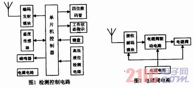
The lid detection circuit is used to realize the liquid level and temperature detection. When the temperature reaches the set value, the buzzer will alarm, indicating that it will be boiled. Please cook the stove to keep the fire off, prevent the pot from drying or drying. When the prompt does not attract attention, when the liquid level reaches the upper limit, an instruction is given to control the solenoid valve to close the gas. If the water is not easy to crotch, etc., when the temperature reaches the set temperature and does not cause attention so that the liquid level is lower than the lower limit of the liquid level, the solenoid valve is also turned off. Once the solenoid valve is closed, manual reset is required to ensure that the accident cannot occur.
The detection control circuit and the solenoid valve circuit communicate wirelessly. The alarm setting temperature can be set using the keyboard. When the four digits work in the setting state, the set temperature is displayed, and the temperature in the pot is displayed in real time during operation. With 220V power supply, the power circuit provides the voltage required for each part.
2 Key hardware technology solutions The key to hardware design is the temperature, liquid level detection circuit, and the coded transmit and receive circuits of the control signals. Mainly given here are the temperature, liquid level detection circuit, and the design idea of ​​the coded transmitting and receiving circuit of the control signal.
The temperature is measured using the DS18B20 digital thermometer. The DS18B20 provides a 9-bit (binary) temperature reading to indicate that the temperature information of the device is sent to or from the DS18B20 via the single-wire interface. Therefore, only one data line and ground line are required from the host CPU to the DS18B20. The power supply can be provided by the data line itself without the need for an external power supply. The DS18B20 measures from -55°C to +125°C with an increment of 0.5, which converts temperature information into numbers in 1 second. The DS18B20 also has two 8-bit memory RAMs for storing measured temperature values, numbered O and 1. If the temperature is negative, the 8th memory of the 1st memory is all 1; otherwise, it is all 0. The O number memory is used to store the complement of the temperature value. The LSB (lowest bit) 1 indicates 0.5. The binary number in the memory is complemented and converted into a decimal number and divided by 2 to obtain the measured temperature. value. Each DS18B20 can be set to two power supply modes, namely data bus power supply mode and external power supply mode. The former can save one wire, but the temperature measurement takes a long time, while the latter uses one wire, but the measurement speed is better. fast. The system is externally powered and packaged in the bottom of the enclosure connected to the ground and extends close to the bottom of the pan.
The liquid level detecting circuit is divided into an upper limit detecting circuit and a lower limit detecting circuit, the upper limit detecting circuit is shown in FIG. 3, and the lower limit detecting circuit is shown in FIG. 4. When the liquid level reaches the upper limit, the upper limit probe is connected to the ground through the liquid, and the 555 timer 2 and 6 feet are pulled low to make the 555 timer 3 pin output a high level. This high level pulls the interface level of U1 and the single chip microcomputer. Low, the MCU detects a low level signal, that is, the liquid level reaches the upper limit processing. When the liquid level reaches the lower limit, the lower limit probe is disconnected from the ground, and the 555 timer 2 and 6 pin potentials become high level. The 555 timer 3 pin outputs a low level, and the single chip detects a low level signal, that is, presses the liquid level. The lower limit is reached. 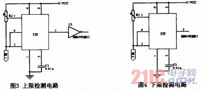
The coded transmit and receive circuit of the control signal encodes and decodes the chip using PT2262/PT2272, of which PT2272 has a latch function. Pins 1~8 of PT2262/PT2272 are the address code setting pins of the chip. The address code has three states: floating, high level, and low level. The address code is like an identification certificate, only the transmitting end. The address codes of the receiving end are set to be identical to each other to confirm each other. Different users use different addresses to ensure that they do not affect each other.
The keyboard of this system mainly has setting/work switching key, temperature+key, temperature-key, reset key, and manual control key. The operating status indication uses four LEDs to indicate the set state, the operating state, the reset state, and the manual state. The four-digit digital tube displays the set temperature value when it is set, and displays the current temperature value when it is working.
Because the receiving decoding module has limited driving capability, a relay is used between the receiving decoding module and the solenoid valve to drive the solenoid valve.
In order to ensure the stability and reliability of the system power supply, the mature switching power supply products are used to supply power to the system, and no additional power supply circuit is designed.
3 software implementation of the system according to the actual composition of the hardware, the software should complete the reading and writing of the DS18B20 digital thermometer, temperature setting, detection and display, whether the liquid level reaches the upper and lower limit detection, keyboard scanning and processing, status indication and alarm , wireless coded signal transmission control and other functions. The software is designed using a modular design approach, setting the initial temperature during power-up initialization and setting the timing interrupt. Keyboard scans, status indications, and digital tube displays are refreshed and processed during a timed interrupt. The specific main program flow chart is shown in Figure 5.
The reading and writing of the DS18B20 digital thermometer in this system is a key to software design. Since the DS18B20 reads and writes data on an I/O line, it has strict timing requirements for the read and write data bits. The DS18B20 has a strict communication protocol to ensure the correctness and integrity of each data transmission. The protocol defines the timing of several signals: initialization timing, read timing, and write timing. All timings use the microcontroller as the master and the single-bus device as the slave. Each command and data transfer starts from the host's active start write sequence. If a single bus device is required to send back data, after the write command, the host needs to start the read sequence to complete the data reception. The transfer of data and commands is low first. The code of the instruction Write Scratchpad (write temporary memory) is 4EH, the code of the instruction Read Scratchpad (read temporary memory) is BEH, the code of the instruction Copy Scratchpad (copy temporary memory) is 48H, and the instruction is Convert Temperature (temperature conversion). The code is 44H, the code for the Recall EPROM is B8H, and the code for the Read Power Supply is B4H. Therefore, the system adopts the module design method for this part of the program, and divides the program into an initialization program, a DS18B20 program, a DS18B20 program, and a temperature conversion program.
4 Conclusion Multi-function pot cover by adding a certain electronic circuit on the basis of the traditional pot cover, effectively avoiding all kinds of accidents, and also liberating people from the care and cooking. This device can be configured either with the lid or on the original lid, which is economical and convenient. The multi-functional lid can also add functions such as stirring and adjusting the fire on the basis of the existing functions, and has high practical value.
This article refers to the address: http://
XLPE Power Cable,Copper Power Cable,33kv Power Cable,XLPE Insulated Cable
Huayuan Gaoke Cable Co.,Ltd. , http://www.bjhygkcable.com