1. What is leakage?
The leakage inductance is the part of the magnetic flux that the primary and secondary of the motor leak during the coupling process.
The leakage induction of the transformer is such that the magnetic lines of force generated by the coil cannot pass through the secondary coil, so the inductance that causes leakage is called leakage inductance.
Where is the leak? Although the printed conductors on the printed circuit board and the lead terminals of the transformer are also part of the leakage inductance, most of the leakage inductance is in the primary winding of the transformer, especially those that are coupled to the secondary winding. in.
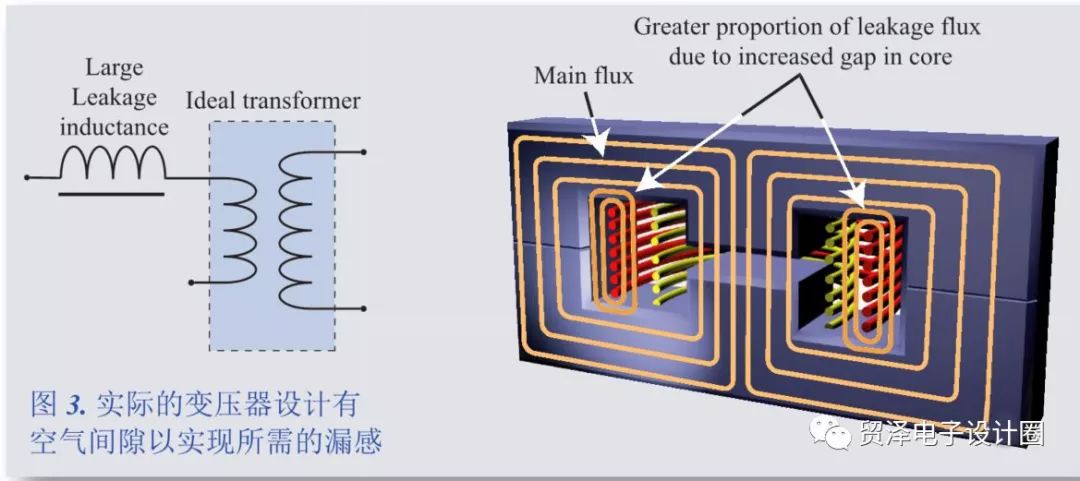
Leakage inductance is the inductance component produced by a transformer's set of coils to another set of magnetic fluxes that are not fully coupled. Any portion of the primary coil to secondary coil that is not coupled to the magnetic flux exhibits an inductive impedance in series with the primary, so in the schematic, the leakage inductance is expressed as an inductance outside the front end of the ideal transformer primary coil.
In certain applications, such as switching power supplies and lighting rectifiers, the leakage inductance of a transformer can have an important functional impact in product design. Therefore, accurate leakage inductance measurement is often an important step for transformer manufacturers.
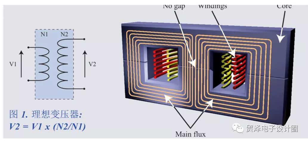
Ideal transformer
Theoretically ideal transformers have no losses. The voltage ratio is directly proportional to the turns ratio, and the current ratio is the reciprocal of the turns ratio (Figure 1).
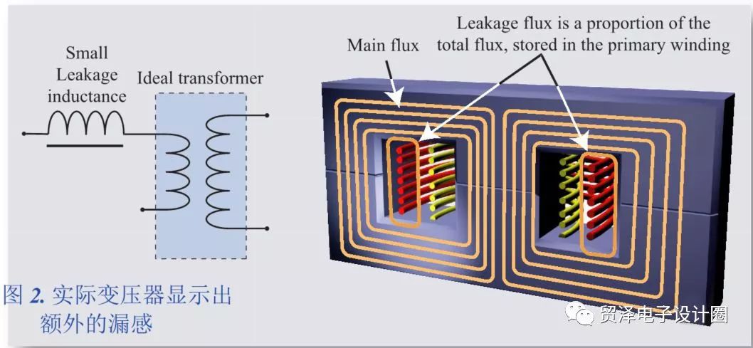
Actual transformer
In an actual transformer, some of the magnetic flux of the primary coil is not coupled to the secondary coil. These "leaked" magnetic fluxes do not participate in the operation of the transformer and can be expressed as an additional inductive impedance in series with the coil (Figure 2).
The actual transformer is added to the air gap
In some transformer designs, the leakage inductance must account for a larger proportion of the total inductance and set a small error. The increase in the leakage inductance ratio is usually achieved by introducing an air gap into the magnetic core, thereby reducing the magnetic permeability of the magnetic core and the inductance of the primary coil. Therefore, the proportion of the magnetic flux uncoupled portion of the primary coil and the secondary coil also increases (Fig. 3).
So is the air gap linearly related to the leakage inductance? 
The following is an example to illustrate the three relationships between transformer leakage inductance and air gap size: constant, large, and small.
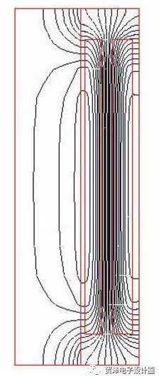
See the figure below, assuming that the air gaps 1, 2, 3 make the magnetic resistance R1 = R2 = R3, ignoring the small part of the magnetic flux of the window, we know
Φ = Φ1 + Φ2.
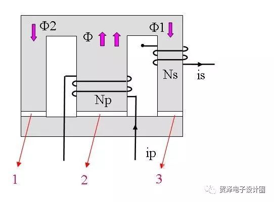
There are three cases:
1. Increase the air gap 1, R1>R3, so that Φ1>Φ2, that is, the magnetic flux coupled to Ns is more, and the leakage inductance is reduced.
2. Increase the air gap 2, R1=R3 is still established, Φ1=Φ2, that is, the magnetic flux coupled to Ns is unchanged, and the leakage inductance is unchanged.
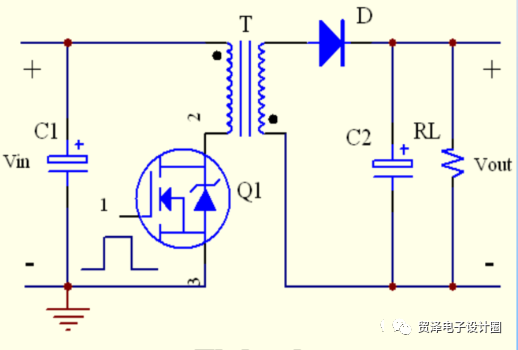
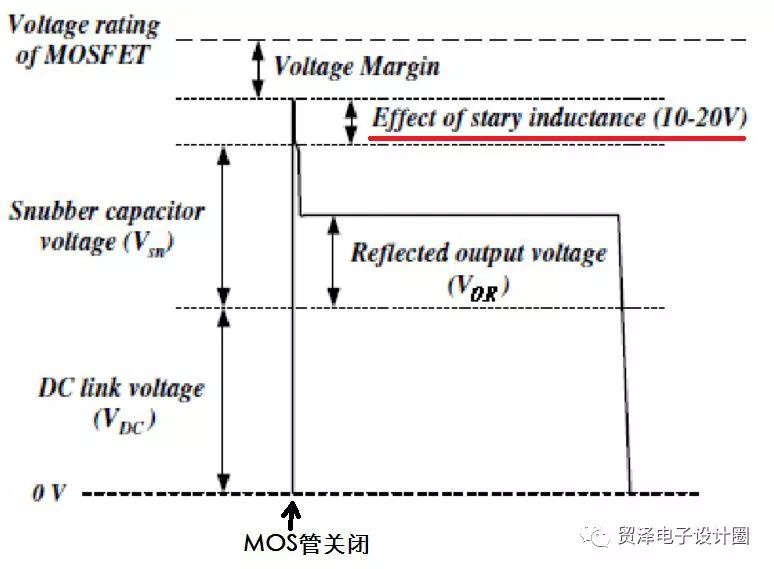
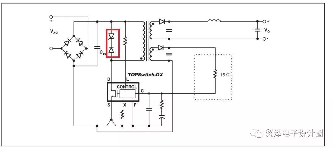
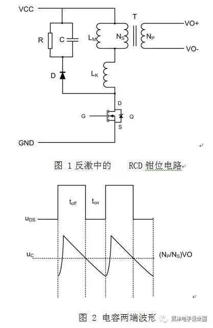
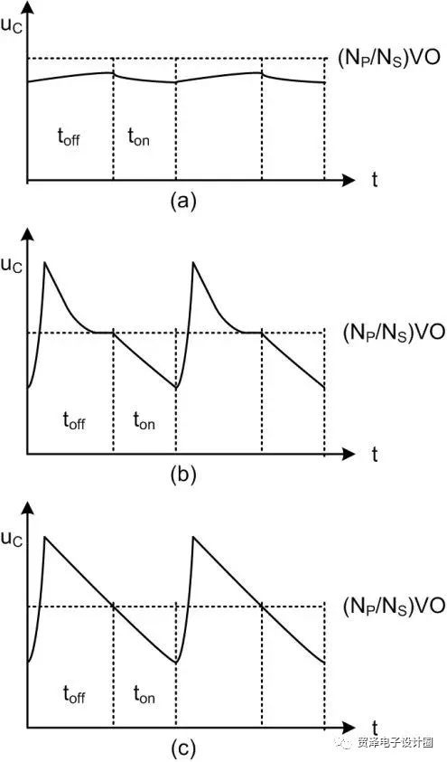
3, increase the air gap 3, R1 The relationship between the leakage inductance of the transformer and the size of the air gap cannot be simply increased, decreased or unchanged. It must be analyzed according to the specific winding structure and core structure. The factor that determines the size of the leak For fixed transformers that have already been fabricated, the leakage inductance is related to the following factors: K: Winding coefficient, proportional to leakage inductance, for simple primary winding and secondary winding, take 3, if the secondary winding is wound with the primary winding, then take 0.85, which is why the recommended method of sandwich winding is recommended. The leakage inductance has dropped a lot, probably less than 1/3 of the original. Lmt: The entire winding is wound around the skeleton and the length of each turn. Therefore, the transformer designer likes to choose the core with the length of the column in the core. The wider the winding, the smaller the leakage inductance. The number of winding turns is kept to a minimum. The degree is very beneficial to reduce the leakage inductance. The influence of the number of turns on the leakage inductance is the relationship of the quadratic. Nx: Number of turns of the winding. W: Winding width, just said already. You can take a very common BOBIN to analyze. Tins: Winding insulation thickness. bW: The thickness of all windings of the fabricated transformer. 2. The harm and protection of leakage inductance Leakage inductance is the measurable inductance that is not coupled to the core or other windings. It is like a separate inductor strung into the circuit. It causes a spike between the DS when the switch is turned off. Because of its flux Unable to be chained by the secondary winding. The leakage inductance can be seen as a parasitic inductance in series with the primary side inductance of the transformer. Therefore, when the switch is turned off, the current in the two inductors is Ipkp, which is the primary side peak current. However, when the switch is turned off, the primary side inductance energy can be transferred to the secondary side (through the output diode) through mutual inductance, but the leakage inductance energy has nowhere to go. Therefore, it will "discharge grievances" in the form of huge voltage spikes. See picture. If you don't try to absorb these leakage energy, the spike will be very high, which will cause the switch to be damaged. Since these energy can't be transmitted to the secondary side, there are only two options: either try to feed back to the input capacitor or try to consume it ( loss). For the sake of simplicity, the latter is usually chosen. Generally, the Zener clamp method can be used directly, as shown in the figure. Of course, the voltage of the Zener diode must be selected according to the maximum voltage that the switch tube can withstand. For some reasons (especially efficiency), it is better to connect the Zener diode in series with the blocking diode and parallel it on the primary side winding. The figure shows. Another approach is to use a capacitive shunt resistor to implement RCD; in most low-power applications, a simple and easy-to-implement RCD clamp circuit is used to mitigate voltage spikes. Therefore, the RCD clamp circuit is mostly used for low power applications because of its simplicity and ease of implementation. Figure 1 and Figure 2 show the voltage waveforms across the RCD clamp circuit and capacitor C in the flyback circuit. The RCD clamp circuit is introduced to consume the leakage inductance energy, but the main excitation inductance energy cannot be consumed, otherwise the circuit efficiency will be reduced. Therefore, the appropriate R and C values ​​should be selected during the circuit design and debugging process so that it is just consumed. Leakage energy. The following will analyze how it works. When the switching tube Q is turned off, the voltage of the primary coil of the transformer is reversed, and the leakage inductance LK releases energy to directly charge C, the voltage of the capacitor C rises rapidly, and C discharges through R after the diode D is turned off. If the C value is large, the voltage on C rises slowly, the secondary side has a small overshoot, and the transformer energy cannot be quickly transmitted to the secondary side. If the C value is particularly large and the voltage peak is less than the secondary side reflected voltage, the voltage on the clamp capacitor will be It is kept near the secondary side reflection voltage, that is, the clamp resistance becomes the load, and the core energy is consumed all the time. At this time, the waveform at both ends of the capacitor is as shown in (a). Waveform at both ends of the capacitor If the RC is too small, the capacitor C will charge faster, and C will discharge quickly through the resistor R. The leakage inductance energy consumption is very fast during the whole process. Before the Q is turned on, the clamp resistor becomes the load of the transformer, consuming the energy stored in the transformer. To reduce efficiency, the waveform at both ends of capacitor C is shown in Figure (b). If the value of RC is appropriate, when the switch Q is turned on again, the voltage on the capacitor C is just placed close to the voltage reflected from the secondary side of the transformer. At this time, the clamping effect is better, and the waveform at both ends of the capacitor C is as shown in (c). Shown. Digital Display Test Pen ,Power Tester Pen,Voltage Pen,Digital Voltage Tester YINTE TOOLS (NINGBO) CO., LTD , https://www.yinte-tools.com