In the design of DC/DC converters, the choice of inductors and capacitors is particularly important. You must fully understand the circuit operation, current path, and what tasks or tasks each device can perform in order to select the appropriate inductor and capacitor. This article gives examples of how to select the appropriate inductor and capacitor for the step-down DC/DC converter from the thinking steps, calculation formulas, and examples.
Inductor selection
The choice of inductor is important when designing a step-down DC/DC converter. Performance or characteristics have a significant impact on their choice. The calculation method of the selection step of the inductance or the inductance value or the like is basically indicated by the technical specifications of the power supply IC.
Inductive selection step
First, the steps for selecting the inductor are described.
1) Calculate the necessary inductance value L
2) Calculate the maximum current flowing to the inductor (output current + 1/2 ripple current)
3) Select the inductor above the maximum current of the calculated inductor saturation current based on the calculated L value (or approximation)
(Note: Calculate the current above the maximum value that may flow out in a short circuit or transient state, so there is a method based on the maximum switching current)
Basically, the decision is made based on the calculation and considering the margin. The method of calculating the margin is based on the company's design rules or rules of thumb.
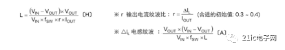
1) Calculation of inductance value First, the inductance value is calculated according to the following formula.
2) Calculation of the maximum current of the inductor Next, the maximum current of the inductor is calculated according to the following formula.
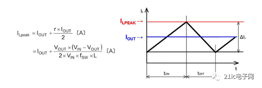
From the formula and current waveform, the ILPEAK value is 1/2 of ΔIL plus the value of IOUT.
An inductor with an approximate inductance value and a saturation current above the maximum current is selected based on the calculated inductance value and the maximum current of the inductor. The following is a selection example.
Selected example of inductance
Conditions: VIN = 12V, VOUT = 3.3V, IOUT = 2A, r = 0.3, f SW = 380kHz
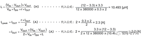
According to the above results, a 10 μH inductance having a saturation current of 2.3 A or more is a starting point. It is called the starting point because this calculation is not absolute and may have to be changed in consideration of a short circuit or a transient state.
Inductor current that changes the inductance value
Here, in order to deepen the understanding of the operation of the inductor, further explain how the inductor current changes when the inductance value changes. The figure below shows ILPEAK with the inductance value set to 0.4μH, 1μH, 2.2μH under the same operating conditions.
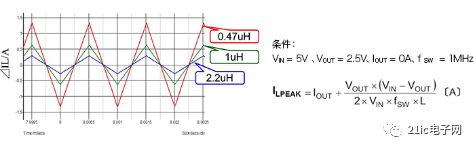
It can also be seen from the formula that when the inductance value L becomes small, ILPEAK will increase and many DC superimposed currents can be obtained. However, with ILPEAK, it is necessary to allow more DC superimposed current. On the contrary, when the inductance value becomes large, it is necessary to discuss the related matters of phase compensation.
Capacitor selection
The capacitors necessary for the step-down DC/DC converter are an output capacitor and an input capacitor. Let's look at the role of the input capacitor and the output capacitor.
First, in order to understand the role of the input capacitor and the output capacitor, first review the current flow of the step-down DC/DC converter. By understanding the different current properties flowing to the various capacitors, it is clear which capacitor should be chosen.
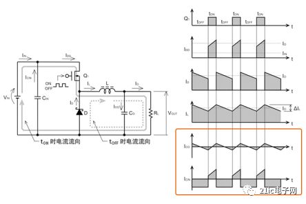
In the figure, the upper ICO is the output capacitor, and the lower ICIN is the current waveform of the input capacitor. The input capacitor can be charged from VIN and the switch current IDD is released when transistor Q1 is ON. Larger currents will flow repeatedly and repeatedly. The output capacitor is repeatedly charged and discharged in conjunction with the output ripple voltage centering on the output voltage.
Output capacitor selection
There are three important factors for selecting the output capacitor.
1) Rated voltage
2) Rated ripple current
3) ESR (equivalent series resistance)
Of course, the voltage and ripple current that the capacitor can apply must be below the maximum rating of the capacitor. In addition, ESR is related to the inductor current and is an important factor in determining the output ripple voltage, so it must be fully explored.
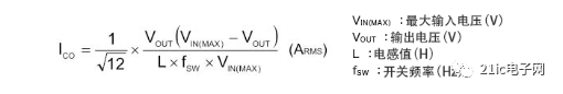
The ripple current of the output capacitor is a triangular wave as shown by the ICO in the figure above, and the effective value is expressed by the following formula.
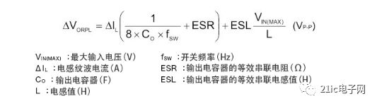
The output ripple voltage is a voltage composite waveform generated by the inductor current IL ripple ΔIL of the above figure and the capacitance of the output capacitor, ESR, and ESL, and is expressed by the following formula.
If represented by a waveform, it is the following image.
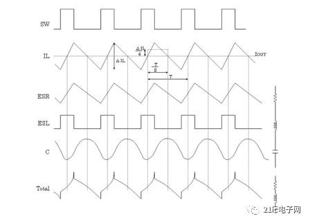
The inductor current ripple ΔIL generated by the switch will produce a ripple voltage that is simply proportional to the ESR. Some ESLs will generate a square wave voltage, which is partially combined with the capacitance value, and the lowest waveform becomes the final output ripple voltage waveform.
The following is a formula indicating the output ripple voltage. Since the ripple voltage of the capacitor and the ripple of the ESR are phase-shifted, it is impossible to perform simple addition, but it is a commonly used formula for estimating the worst value of the ripple voltage.

According to this formula, if the output ripple voltage is to be small, the ESR must be lowered, the output capacitor should be increased, and the switching frequency should be increased to make the IL at the minimum necessary.
In recent years, the use of laminated ceramic capacitors in output capacitors seems to be increasing. Ceramic capacitors Because the ESR and ESL are very small, the observable ripple voltage is almost always derived from the capacitance value.
In summary, the rated voltage, rated ripple current, and ESR are all important factors in the selection of the output capacitor. In addition to smoothing and stabilization, it is of course closely related to the output ripple voltage.
Input capacitor selection
The main points of the function and selection of the output capacitor have been explained above. Next, enter the description of the input capacitor.
There are also three important factors for selecting the input capacitor.
1) Rated voltage
2) Rated ripple current and ripple heating characteristics
3) When using ceramic capacitors: temperature characteristics and DC offset characteristics
In addition, please note the following points before choosing:
・The rated voltage must be higher than the maximum input voltage.
• The rated ripple current must be greater than the maximum input ripple current that occurs at the IC input.
• In a buck converter, the maximum value of the instantaneous input current is the same as the output current.
The ripple current effect value ICIN flowing to the input capacitor is expressed by the following formula.

This result is mainly based on the selection of the capacitors according to the graph of the absolute maximum rating of the capacitor ripple current and the ripple heating characteristics.
The input ripple voltage ΔVIN is calculated using the following formula.
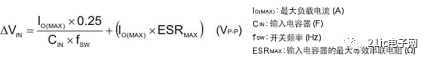
According to this formula, if the input capacitor becomes large, the input ripple voltage becomes small.
A ceramic capacitor can be selected as the input capacitor. When using ceramic capacitors, it is generally necessary to pay attention to changes in capacitors caused by temperature changes and DC offsets.
For the temperature characteristics, if the CLASS2 (high dielectric constant type) type EAI symbol X5R (-55 ~ +85 ° C, capacitance value change rate ± 15%) or X7R (-55 ~ +125 ° C, capacitance value change rate ± 15%), sufficient temperature characteristics can be obtained.
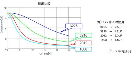
Regarding the DC offset, of course, it is necessary to select a small influence, but even if the capacitance value and the withstand voltage are the same, the variation characteristics vary depending on the package size. The chart below is an example of this, and the display size is small. In short, be sure to get sufficient information from the capacitor manufacturer.
Basically, it is necessary to select an input capacitor based on these information. However, it is necessary to confirm that the input voltage to which the ripple is applied does not exceed the withstand voltage and that there is no unacceptable heat due to the ripple current.
To sum up, when selecting an input capacitor, the key considerations are rated voltage, rated ripple current, ripple heating characteristics, especially temperature characteristics and DC bias characteristics of ceramic capacitors.
With more than 15+ yrs rich MFG experience, you can definitely trust in and cooperate with.
Provide you with the supply of personal protective equipment. to help you safely get back to your daily routine.
Our products include pulse Oximeter Finger, Forehead Thermometer, Automatic foam soap dispenser, etc.
Our strict quality control protocol thoroughly vets every aspect of production, storage, and shipments all the way way to our end customers.
protective equipment, ppe personal protective equipment, definition of personal protective equipment
TOPNOTCH INTERNATIONAL GROUP LIMITED , https://www.itopnoobluetoothes.com