With a variety of the latest micro-power, high-precision IC chips, you can design a more complete low-power heart rate monitor (HRM). This article is intended to discuss these chips and features.
The strict requirements for designing a portable heart rate monitor are enough to cause headaches for anyone. First, the heart monitor must meet the highest standards of safety, reliability, and precision. Designers must also deal with the limited amount of battery power in the button battery. On the one hand, to meet the market's demand for more functions, on the other hand, it can not increase the space, power or cost, and the headaches come one after another.
Fortunately, the solution is there. With a variety of the latest micro-power, high-precision IC chips, you can design a more complete low-power heart rate monitor (HRM).
The most important function of low-power ICs is to extend the life of the batteries used in HRM. HRM is used to measure the heart rate of patients in real time, or to record heart rate for later research. Portable HRMs rely on batteries for long periods of time and therefore require low power consumption. Dynamic ECG monitors and other portable ECG systems have been powered by low-voltage batteries for decades to ensure safety. What is most unwanted for heart patients or sensitive devices is the sudden emergence of "hot" line voltages. Micropower ICs operate at low voltages and currents, thus saving battery power.
HRM analog front end
The main purpose of HRM is to calculate the heart rate and display the ECG waveform, and also to provide lead-off detection. Figure 1 shows a block diagram of the HRM design. The analog front end is built using the following devices: a micropower instrumentation amplifier, an operational amplifier, and a microconverter with a 12-bit ADC, sample-and-hold amplifier, and digital processor. The processed data is sent to the PC for display.
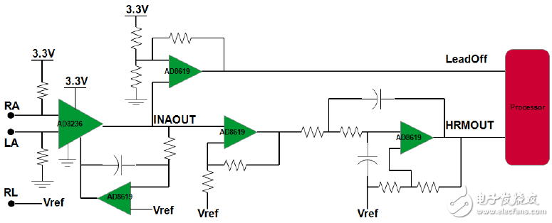
Figure 1. Micropower instrumentation amplifier forms an excellent heart rate monitor input amplifier
Micropower instrumentation amplifiers form an excellent input amplifier with low power consumption, small size, high common-mode rejection ratio (CMMR), rail-to-rail input and output over the entire frequency range, and are ideal for this battery-powered application. High-performance micropower instrumentation amplifiers solve many common human skin potential (ranging from 0.2 mV to 2 mV) measurement challenges. For this application, the best instrumentation amplifier should have a high CMMR in order to suppress common mode signals, such as line noise or high frequency EMI in operating room equipment. The rail-to-rail output feature provides a wide dynamic range and supports higher gain than typical instrumentation amplifiers. In addition, designers should use a micropower instrumentation amplifier to implement a natural RC filter; this RC filter can reduce high frequency noise when the amplifier uses a series input resistor before.
In the main signal chain, the micropower instrumentation amplifier is followed by an integrator feedback network, implemented with a 4.7 μF capacitor and a 100 kΩ resistor to set the −3 dB cutoff frequency of the high-pass filter. It suppresses the differential DC offset that can be generated by the electrode's half-cell overpotential. The micropower op amp provides 13 times the extra gain to amplify the weak signal. An active second-order low-pass Bessel filter removes signals above approximately 50 Hz.
Since the circuit is battery powered, the circuit's reference voltage can be used as a reference voltage when connected to the patient, improving common-mode rejection. This is important for measuring ECG signals. Note that some machines get power from the pedals, so no isolation is used.
The reference voltage
This design assumes an ECG signal range of 0.2 mV to 2 mV. To prevent the signal from being clamped and maximizing the dynamic range of the ADC (0 V to 1.25 V), the design adds 0.625 V bias. As shown in Figure 2, the resistor divider and buffer generate a 0.625 V reference, which is also used to bias the ECG signal (see Figure 1).
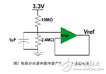
Figure 2. Resistor Divider and Buffer Generate 0.625 V Reference
Lead drop detection
If the electrode is not in good contact, the HRM should provide a warning signal. These resistors, together with the two 20 MΩ resistors at the input of the micropower instrumentation amplifier (see Figure 1), offset the input when the electrodes are removed from the patient. In normal operation, the output of the micropower instrumentation amplifier is the reference voltage; if one electrode falls off, the output will become 0V. Figure 3 shows the lead-off detection circuit. The output of the micropower instrumentation amplifier is connected to the input of the detection circuit.
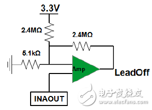
Figure 3. The instrumentation amplifier output is connected to the input of the lead-off detection circuit
In fact, the lead-off detection circuit is a comparator, and hysteresis is implemented using an amplifier. A high gain comparator is used to determine if the input voltage is above or below the reference voltage and to output a voltage representative of the sign of the net difference. Hysteresis eliminates noise-induced instability with a small amount of positive feedback. When operating from a single supply, the reference voltage needs to be offset to allow the circuit to operate completely in the first quadrant. Figure 4 shows the implementation. The resistor dividers (R2 and R1) generate a positive reference voltage for comparison with the input voltage. The formula used to design the DC threshold is given in Figure 4.
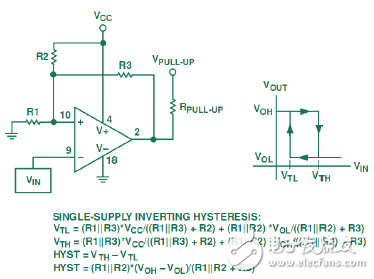
Figure 4. How the comparator works under single-supply conditions
Referring to Figure 3, R1 = 5.1 kΩ, R2 = R3 = 2.4 MΩ, VCC = 3.3 V, VOL = 0 V, VOH = 3.3 V.
We use the formula in Figure 4 to calculate: VTL = 0.006983 V
VTH = 0.013966 V
Hysteresis = VTH – VTL = 0.006983 V
In normal operation, the output of the micropower instrumentation amplifier should be VREF; if the lead is off, the output of the comparator will be 0V. When the output of the comparator rises to 3.3 V, the output of the micropower instrumentation amplifier is also 0 V. Depending on the interrupt mode of the microcontroller, a rising edge or high level can trigger a microcontroller interrupt. When the lead is connected again, the output of the comparator drops to 0 V, and a falling or low level can trigger an interrupt.
Hydraulic High Pressure Sensor
Hydraulic High Pressure Sensor,Thin Film Pressure Sensor,Vacuum Transducer,Brake Fluid Pressure Sensor
Shenzhen Ever-smart Sensor Technology Co., LTD , https://www.fluhandy.com