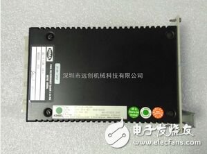
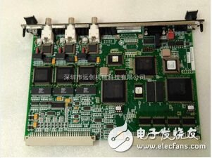
During the input sampling phase, the PLC reads all input states and data in a scan mode and stores them in the corresponding cells in the I/O map area. After the input sampling is finished, it is transferred to the user program execution and output refresh phase. In these two phases, the status and data of the corresponding unit in the I/O map area does not change even if the input status and data change. Therefore, if the input is a pulse signal, the width of the pulse signal must be greater than one scan period to ensure that the input can be read in any case. F8652X-HIMA analog output module E

The PLC adopts the "sequential scanning, continuous cycling" working mode: (1) each scanning process, centralized collection of input signals, centralized refreshing of the output signal; (2) input refresh process, when the input port is closed, the program is input during the execution phase There is a new state at the end and the new state cannot be read in. Only when the program performs the next scan, the new state is read; (3) one scan cycle is divided into input sample, program execution, and output refresh; (4) the content of the component map register changes as the program execution changes. (5) The length of the scan cycle is determined by three: 1) the speed at which the CPU executes the command; 2 refers to the time occupied by itself; 3 the number of instructions, the current PLC scan speed is very fast. (6) Due to the centralized sampling and centralized output mode, there is a phenomenon of input/output lag, that is, input/output response delay.
The PLC originally developed and produced is mainly used to replace the traditional control device composed of relay contactors, but the operation modes of the two are different:
(1) The relay control device adopts the way of parallel operation of hard logic, that is, if the coil of this relay is energized or de-energized, at which position of the relay control line all contacts of the relay (including its normally open or normally closed contact) Will act immediately at the same time.
(2) The CPU of the PLC uses sequential logic to scan the operation mode of the user program, that is, if an output coil or logic coil is turned on or off, all contacts of the coil (including its normally open or normally closed contacts) are not It will act immediately and must wait until the contact is scanned.
In order to eliminate the difference between the two due to different operating modes, considering that the action time of various contacts of the relay control device is generally above 100ms, and the time for PLC scanning user program is generally less than 100ms, therefore, the PLC adopts one. It is different from the operation mode of a general microcomputer---scanning technology. Thus, in the case where the I/O response is not high, there is no difference in the processing results between the PLC and the relay control device.
1. Scanning technology When the PLC is put into operation, its working process is generally divided into three stages, namely, input sampling, user program execution and output refreshing. Completing the above three phases is called a scan cycle. During the entire operation, the CPU of the PLC repeatedly executes the above three stages at a certain scanning speed.
3500/05 System Framework
3500/06 protective box
3500/08 Troubleshooting Connection Panel
3500 internal safety barrier
3500 electrical insulation device interface
3500/15 power supply
3500/20 frame interface module
3500/22M frame interface module with TDI
3500/25 phase sensor module
3500/32 4-channel relay module
3500/34 TMR Relay Module
3500/40M Proximitor Displacement Monitor
3500/42M displacement/speed acceleration monitoring
3500/44M aerodynamic monitor
3500/45 differential expansion / axial position monitor
3500/46M hydropower monitor
3500/50 speed module
3500/53 overspeed detection module
3500/60 and 3500/61 temperature monitors
3500/62 Process Variable Monitor
3500/64M dynamic pressure monitor
3500/72M piston rod position monitor
3500/77M cylinder pressure monitor
3500/90 communication gateway
3500/92 Communication Gateway
3500/93 LCD display unit
3500/94 VGA display unit
3500/95 User Interface Workstation
American Bently Bentley 3500 Series Monitoring Module
4-channel displacement monitor module 3500/40-01-00 176449-01 after 125680-01
Vibration module 3500/42-01-00 176449-02 after 128229-01
Power module 3500/15-02-02-00 127610-01 before +125840-01
Frame interface module 3500/22-01-02-00 138607-01 after 146031-02
Key phase sensor module 3500/25-01-01-00 149369-01 after 125800-01
Relay module 3500/32-01-00 125712-01 after 125720-01
Frame interface module 3500/20-01-01-00
Frame interface module 3500/20-01-02-00
Frame interface module 3500/20-02-02-00
Frame interface module 3500/22-01-01-00
Key phase sensor module 3500/25-01-01-00
Key phaser module 3500/25-01-02-00
Key phaser module 3500/25-01-03-00
Power module 3500/15-02-02-00
Key phaser module 3500/25-01-03-00
Relay Module 3500/32-01-00
Key phaser module 3500/33-01-00
4-channel displacement monitor module 3500/40 (140734-01, 135489-04)
Vibration module 3500/42-01-00
Vibration module 3500/42-04-00
Vibration module 3500/42-09-00
Differential expansion / axial position module 3500/45-01
Differential expansion / axial position module 3500/45-01-00
Differential expansion / axial position module 3500/45-01-00
Speed ​​module 3500/50-01-00
Bentley 3500 Monitoring Module
Speed ​​module 3500/50-01-00-01
Speed ​​module 3500/50-01-00-01
Speed ​​module 3500/50-01-00-02
Speed ​​module 3500/50-01-01-00-00
Speed ​​module 3500/50-04-00
Overspeed protection module 3500/53-01-00
Temperature monitor 3500/61 (133819-02)
Temperature monitor 3500/61 (163179-02)
Temperature monitor 3500/61 (163179-03)
Temperature monitor 3500/61-01-00 (163179-02)
Instrument frame 3500/05-01-01-00-00-00
Instrument frame 3500/05-01-02-00-00-00
Instrument frame 3500/05-01-02-00-01
Instrument frame 3500/05-02-04-00-00-00
Power module 3500/15-02-02-00
Frame interface module 3500/20-01-01-00
Frame interface module 3500/20-01-02-00
Frame interface module 3500/20-02-02-00
Frame interface module 3500/22-01-01-00
Key phase sensor module 3500/25-01-01-00
Monitoring module 3300/50-01-01-00-00
Monitoring module 3300/50-02-01-00-00
Monitoring module 3300/52-02-00-00
Monitoring module 3304.03-03-02-**-**
Bently module 3350/5-03-01-15-15-00-00-01-00
Bently module 3350/5-03-04-15-15-00-00-05-00
Bently module 3300/65-14-01-00-00-01
Power module 3500/15-02-02-00 127610-01 before +125840-01
Frame interface module 3500/22-01-02-00 138607-01 after 146031-02
Key phase sensor module 3500/25-01-01-00 149369-01 after 125800-01
Relay module 3500/32-01-00 125712-01 after 125720-01
4-channel displacement monitor module 3500/40-01-00 176449-01 after 125680-01
Vibration module 3500/42-01-00 176449-02 after 128229-01
Bentley 3500 System
Power module 3500/15-02-02-00
Frame interface module 3500/20-01-01-00
Frame interface module 3500/20-01-02-00
Frame interface module 3500/20-02-02-00
Frame interface module 3500/22-01-01-00
Key phase sensor module 3500/25-01-01-00
Key phaser module 3500/25-01-02-00
Key phaser module 3500/25-01-03-00
Relay Module 3500/32-01-00
Key phaser module 3500/33-01-00
4-channel displacement monitor module 3500/40 (140734-01, 135489-04)
Vibration module 3500/42-01-00
Vibration module 3500/42-04-00
Vibration module 3500/42-09-00
Differential expansion / axial position module 3500/45-01
Differential expansion / axial position module 3500/45-01-00
Differential expansion / axial position module 3500/45-01-00
Speed ​​module 3500/50-01-00
Speed ​​module 3500/50-01-00-01
Speed ​​module 3500/50-01-00-01
Speed ​​module 3500/50-01-00-02
Speed ​​module 3500/50-01-01-00-00
Speed ​​module 3500/50-04-00
Overspeed protection module 3500/53-01-00
Temperature monitor 3500/61 (133819-02)
Temperature monitor 3500/61 (163179-02)
Temperature monitor 3500/61 (163179-03)
Temperature monitor 3500/61-01-00 (163179-02&133819-02)
Temperature monitor 3500/61-03-00
Temperature monitor 3500/61-03-00
Process Variable Monitoring Module 3500/62 (136294-01)
Process Variable Monitoring Module 3500/62-03-00 (163179-03&136294-01)
Monitoring module 3500/63-01-00
Communication Gateway Module 3500/92-01-01
Communication Gateway Module 3500/92-01-01-00
Communication Gateway Module 3500/92-02-01-00
Communication Gateway Module 3500/92-04-01-00
Display device 3500/93-01-00-00-00
Display device 3500/93-01-00-00-00
Display device 3500/93-02-02-02-00
Display device 3500/93-03-01-00
Display device 3500/93-03-01-00-00
Display device 3500/93-03-01-00-00
Display device 3500/93-07-01-02-00
Monitoring module 3500-40-01-00
Key phase channel vibration monitor 3300/16-15-01-03-00-00
Dual channel vibration monitor 3300/16-15-01-03-00-00-00
Monitoring module 3300/20-12-01-00-00-00
Monitoring module 3300/20-12-01-01-00-02-00
Monitoring module 3300/20-12-01-03-00
Supply the US BENTLY Bentley 350020 frame interface module,
BENTLY Bentley 350025 improved key phase module,
BENTLY Bentley 190065A Vibration Monitor
BENTLY Bentley 3300 vibration probe,
BENTLY Bentley 350015 power module, 50032BENTLY Bentley 4-channel relay module,
BENTLY Bentley 350042M speed acceleration monitoring module,
BENTLY Bentley 350046M hydroelectric monitor,
BENTLY Bentley 350053 overspeed monitoring module,
BENTLY Bentley 350062 Process Variable Monitor
BENTLY Bentley 350005 frame,
BENTLY Bentley 350042M Displacement Monitor,
BENTLY Bentley 350034 relay module,
BENTLY Bentley 350045 Differential-Axial Position Monitor,
Bentley 3500/64M Dynamic Pressure Monitor
BENTLY Bentley 350050 speed module,
BENTLY Bentley 350072M piston rod position monitor,
BENTLY Bentley 350042M Pressure Monitor,
BENTLY Bentley 350077M cylinder pressure monitor,
BENTLY Bentley 350092 communication module,
BENTLY Bentley 350093 display module,


Usually,10 & 20 layers PCB are HDI board,but some are not .Some with big trace width and space,holes are over 0.3mm too. We have much experience in doing 10 layer PCB & 20 layer PCB.
A ten-layer board should be used when six routing layers are required. Ten-layer boards, therefore, usually have six signal layers and four planes. Having more than six signal layers on a ten-layer board is not recommended. Ten-layers is also the largest number of layers that can usually be conveniently fabricated in a 0.062" thick board. Occasionally you will see a twelve-layer board fabricated as a 0.062" thick board, but the number of fabricators capable of producing it are limited..
High layer count boards (ten +) require thin dielectrics (typically 0.006" or less on a 0.062" thick board) and therefore they automatically have tight coupling between layers. When properly stacked and routed they can meet all of our objectives and will have excellent EMC performance and signal integrity.
A very common and nearly ideal stack-up for a ten-layer board is shown in Figure 12. The reason that this stack-up has such good performance is the tight coupling of the signal and return planes, the shielding of the high-speed signal layers, the existence of multiple ground planes, as well as a tightly coupled power/ground plane pair in the center of the board. High-speed signals normally would be routed on the signal layers buried between planes (layers 3-4 and 7-8 in this case).
10 layer PCB 10 layer TG170 PCB 10 layer design
Storm Circuit Technology Ltd , https://www.stormpcb.com