This article will introduce a switching constant current source application circuit diagram, which is composed of W723 multi-terminal adjustable positive integrated voltage regulator, output current 1A. In the circuit shown, W723 reference voltage (about 7.2V) A voltage of about 3V is applied to the non-inverting input through the voltage division of R1 and R2, and is also divided by the resistors R3 and R4 and then applied to the inverting input terminal. The low terminal of R4 is connected to the shunt resistor R5. When the inverting and non-inverting inputs are approximately balanced, the voltage drop across shunt resistor R5 is around 1V. R6 is used to regulate the output ripple current. When the feedback current of the circuit increases, the output stage of the voltage regulator unit is turned on, and the Uin terminal of W723 has a current pulse of 12 mA, driving the transistor VT. The voltage regulator diode VD1 is used to bias the output stage of the voltage regulator unit, and the diode VD2 It is used to eliminate reverse spikes. Capacitor C1 and inductor L form a filter to smooth the switching output waveform. The maximum operating frequency of the circuit depends on the size of the load, typically 20 kHz. See the figure below. 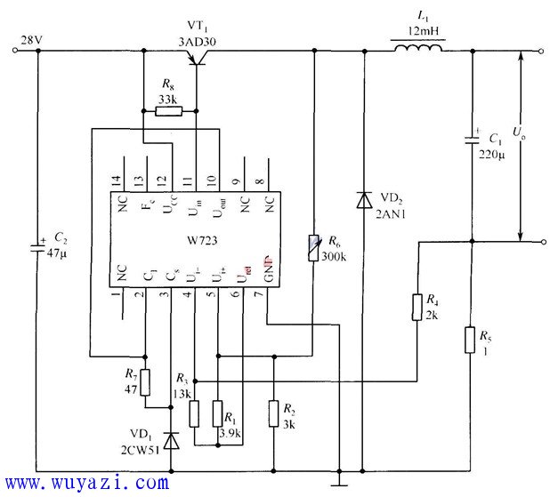
Previous: External conversion circuit when DAC0832 outputs analog voltage
Next:32W fluorescent lamp ballast circuit diagram
Related Reading Filter Drives Zener Diode Crystal Transistor Integrated Regulator
- • [Technical Information] Hongli and Japan OKI expand cooperation 0.22 micron flash memory process for fingerprint authentication accelerator 2016-08-10 14:18
- • [Technical Information] Chartered Acquires Hitachi Singapore Fab to Expand Capacity Expansion Business 2016-08-10 14:18
- • [Technical Information] SanDisk and Toshiba release 41% increase in integration of 3bit NAND flash technology per unit 2016-08-10 14:18
- • [Technical Information] Hitachi and Renesas develop new technology system LSI on-chip SRAM power consumption reduction of 40% 2016-08-10 14:18
- • [Technical Information] Sharp Alliance Tokyo Electronics enters the solar cell equipment market 2016-08-10 14:18
- • [Technical Information] In 2007, the top ten units of China's electronic special equipment industry were released 2016-08-10 14:18
- • [Technical Information] Tianwei Baole Leshan Power and US Company Signed 40 Million Euros to Order Polysilicon Equipment 2016-08-10 14:18
- • [Technical Information] Dow Corning Silicon Polymer Resin Capability Doubles More Manufacturers Benefit from Advanced Photoresist 2016-08-10 14:18
0.8mm Pin Header
Antenk 0.8mm Pitch Male Header series is a fine pitch, low profile, single/dual/three/four row, PCB mounted connector set intended for limited space applications or where total weight is a factor. Our specially tooled insulators and contacts maintain consistent high quality through our automated production processes. Each series is available in thru-hole PCB or SMT mounting and plated tin, gold or selective gold as specified.
0.8mm Pin Header Options
Number of Rows
1/Single
2/Double
3/Three
4/Quad
Number of Positions
2 Position
3 Position
4 Position
5 Position
6 Position
8 Position
10 Position
12 Position
14 Position
15 Position
16 Position
17 Position
20 Position
Termination Style
SMD/SMT
Through Hole
Mounting Angle
Right Angle
Straight
0.8mm Pin Header Specifications:
Material: Standard Hi-Temp insulator: Nylon 6T, rated UL94V-0
Insulator Color: Black
Contacts: Phosphor Bronze
Plating:
U = Gold over nickel underplate
SG = Gold over nickel underplate on
contact area, tin over copper underplate on tails.
T = Tin over copper underplate overall.
Electrical:
Operating voltage: 250V AC max.
Current rating: 1 Amp max
Contact resistance: 20 mΩ max. initial
Insulation resistance: 5000 MΩ min.
Dielectric withstanding voltage: 1000V AC for 1 minute
Mechanical:
Mating durability: 500 cycles min.
Temperature Ratings: Operating temperature: -40°C to +105°C
Max process temp: 230°C for 30 ~ 60 seconds (260°C for 10 seconds)
Soldering process temperature: 260°C
Packaging:
Anti-ESD plastic bags or tubes
Approvals and Certifications:
UL Recognized File no. E224053
Pin Header,0.8Mm Male Header,0.8Mm Pin Header,0.8Mm Male Header Pins,0.8mm Pitch Pin Header,SMT 0.8mm Pin Header, THT 0.8mm Pin Header
ShenZhen Antenk Electronics Co,Ltd , https://www.coincellholder.com