In the process after soldering the capacitor on the board, if the board is bent during operation, the capacitor may be broken. In order to avoid this, it is better to install the capacitor in the opposite direction of the curved part of the board. This article will introduce the method of mounting the parts that apply pressure to the warpage or bending of the board.
1) Circuit board pressing direction and part mounting directionFigure 1 is an example of longitudinal and lateral assembly of parts for the direction in which the board is pressed. Facing the direction of the pressure, laterally mounting the parts slows down the pressure from the board.
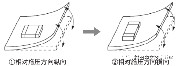
Figure 1 Circuit board pressing direction and part assembly orientation
The evaluation results of 1, 2 and 2 in Fig. 1 are shown in Fig. 2 by the resistance to the board bending test. It can be seen that by being assembled in the two directions, the bending resistance of the board is increased, and it is difficult to apply pressure to the parts.

Figure 2 Relationship between part mounting direction and residual rate
2) Capacitor installation near the crack of the boardCircuit board cracks or circuit board cutouts are the most likely to cause voltage on the board during the production process. For example, when assembling parts in the vicinity of the crack in the circuit board as shown in Fig. 3, if they are assembled in the order of B, D < C < A, they are easily subjected to pressure.
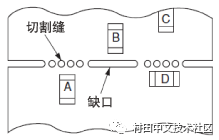
Figure 3 Example of installation of parts near the crack of the board
So, let's look at the degree of deformation of the board when there is no gap.
What is the difference in board bending when there are no gaps? The FEM analysis results are shown in Figures 4 and 5.
Imagine the case of assembling a part at the position shown in the model diagram. (Circuit board 1.6mm thick FR4)
Figure 4 shows the case without a gap. The pressure on the board is large, and red-yellow tensile stress is generated at the board assembly position, and the capacitor may be cracked.
On the other hand, Fig. 5 shows a case where there is a notch, and it can be seen that the position of the mounted component is green, and the circuit board hardly bends. The pressure applied to the part can be controlled to a relatively small range, so it is an effective way to avoid cracking of the capacitor. In summary, the pressure is relieved by the board notch, and it is most effective to arrange the part orientation (D in Fig. 3) in parallel with the notch line. In addition, when the orientation of the part cannot be changed, it is recommended to set the notch to make the board less susceptible to deformation (B in Fig. 3).
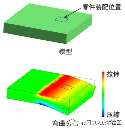
Figure 4 No-notch model and bending distribution

Figure 5: Notched model and curved distribution
23.8 & 24 Inch Aio,Aio Pc,All In One Gaming Pc,Touch Screen Computer
Guangzhou Bolei Electronic Technology Co., Ltd. , https://www.nzpal.com