The Application of Serial RapidIO in WiMAX Base Station System
With the full deployment of 3G mobile communications represented by TD-SCDMA and WCDMA, the LTE standard has basically been completed, and Huawei and Ericsson have successfully implemented a live demonstration of the LTE standard. , Standards and systems development has also begun.
Compared with traditional 3G standards of TD-SCDMA, WCDMA and CDMA2000, WiMAX (Worldwide Interoperability for Microwave Access) has a maximum transmission radius of up to 50 kilometers, nearly twice the former. In terms of transmission speed, WiMAX also makes other 3G standards unmatched. Within 10 kilometers, the speed of the WiMAX network can reach 75 Mbit / s. In addition, WiMAX and other wireless communication systems need to support a large number of broadband users and extremely high air interface rates, use complex communication signal processing algorithms such as MIMO, OFDM, and have dynamic reconfiguration, dynamic scheduling of computing resources, and calculation of base stations. Handling and interconnection place extremely high demands. This high-performance wireless communication system has great difficulties and challenges in implementation. A typical wireless base station system is composed of CPU, DSP and FPGA. As the performance of processors such as CPUs, DSPs, and FPGAs has been greatly improved, improving the performance of the bus connecting these high-performance devices has become the key to improving system performance. The wireless base station system based on Serial RapidIO proposed in this paper solves this problem. The system can achieve a transmission speed of 10Gbit / s and is suitable for new wireless base station systems such as WiMAX.
Processor selection
The real-time processing capability of the system mainly depends on the computing power, storage configuration and interconnection topology of a single processor. The mainstream processors currently used in embedded systems are GPP / RISC, DSP and FPGA. In order to select the best processor, comprehensive consideration is needed from factors such as computing power, ease of programming, power consumption, effective bandwidth, and fully defined interfaces. Therefore, the author chooses the system architecture with MPC8548, TMS320C6455 as the main processor and Xilinx FPGA V5LX110 as the slave processor.
The MPC8548 processor uses an e500v2 core with a maximum rate of 1.5GHz, integrated L1 / L2 two-level cache, and integrated serial RapidIO and PCI Express high-speed interconnect interfaces, supporting 4x serial RapidIO. It is suitable for the transmission processing performance of gigahertz or more and the advanced functions of highly integrated and high-speed connection.
TMS320C6455 is a chip with high calculation speed and low power consumption of TI. The processing speed of C6455 is 9600MIPS. Considering the practicability and bandwidth of the interface, C6455 integrates a 4-channel serial RapidIO (SRIO), this interface has a throughput of 25Gbit / s. The peripheral bus of TMS320CC6455 also includes: two multi-buffered serial bus (McBSPs), a 10/100 / 1000M Ethernet media access controller (EMAC), a seamless external memory interface (64bit EMIFA), and a 32-bit DDR2 SDRAM Interface etc. The rich peripheral bus makes the design based on C6455 flexible, supports strong storage capacity and high-speed data transmission, and is suitable for base station system design such as 3G and WiMAX.
Serial RapidIO features
The RapidIO interface based on TMS320C645x is called SRIO (Serial RapidIO). SRIO has the following characteristics: less pins; low power consumption; SRIO protocol stack is simple, software overhead is small; data width and speed are adjustable with DMA and message passing function; support complex and adjustable topology; support multi-point transmission; reliable High quality, can provide service quality assurance.
The above features of SRIO have great application prospects in real-time signal processing systems. SRIO supports 1x and 4x modes. The 1x mode supports one channel with operating speeds of 1.125Gbaud, 2.5Gbaud, and 3.125Gbaud. The 4x mode supports 4-channel SRIO links, which can provide 10Gbit / s of traffic and ensure data integrity. Because SRIO packet processing is implemented through hardware, this means that I / O processing overhead can be greatly reduced, latency can be reduced, and system bandwidth can be increased. But unlike most bus interfaces, the SRIO interface has fewer pins and the bandwidth can continue to expand on the basis of a link of 3.125baud.
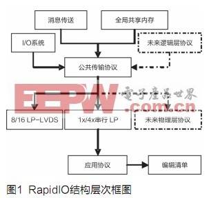
The Serial RapidIO protocol is a point-to-point packet exchange protocol, consisting of packets and control symbols. SRIO has a three-layer structure of physical layer, transport layer and logical layer. The logic layer defines the overall protocol and packet format; the transport layer provides routing and addressing functions for RapidIO packets; the physical layer is responsible for describing the interface specifications of the device. The hierarchical division of the structure ensures that new transaction types can be added at any layer without changing other layer specifications, which is helpful for design flexibility and better front-to-back compatibility. Figure 1 illustrates the layered structure of the SRIO protocol.
SRIO working mode is divided into: I / O logic operation and message operation.
In I / O mode, all packets contain specific addresses, and the addresses indicate that the data should be stored in the destination device. Direct I / O requires that the RapidIO source device must have the memory address table of the destination device. When the CPU needs to send data from the local memory to the external processing unit, the CPU must provide the SRIO interface with information about the transfer, such as: DSP memory address, target deviceID, destination address, packet priority, etc.
In message transfer mode, the source of the message does not need to know the internal structure or memory map of the target device. Instead, RapidIO packets are marked with mailbox. Mailbox is controlled by the local device and mapped to a memory address. For communication between the two processors, the sending processor writes to the local message mailbox, the mailbox reads the information of the local memory to be sent, and sends the information to the receiving processor's local mailbox. The receiving mailbox saves the information in local storage and notifies the receiving processor that the message has arrived. The receiving processor then accesses its local memory to read the message.
Wireless base station system design
Wireless base stations are typical high-performance embedded communication systems. They have very high requirements for interconnection bandwidth, delay, complexity, flexibility, and reliability. Serial RapidIO is the best choice to meet these requirements.
Wireless base station system
In the traditional base station system, the interconnection between DSP and PowerPC or FPGA generally uses the external memory interface EMIF; the DSP or the DSP and the host generally use HPI (Host Port Interface) or PCI interconnection. Their main disadvantages are: small bandwidth, multiple signal lines, master-slave mode interface, does not support peer-to-peer transmission. In addition, the DSP cannot directly transmit the backplane. If you use serial RapidIO for DSP interconnection, you can greatly improve efficiency. First, it can minimize the number of signal pins used to achieve high-speed interconnection between DSPs. Second, it can simplify communication between processors, thereby Effectively reduce system cost.
The system shown in Figure 2 is a high-performance DSP system based on CPU. PowerPC is mainly aimed at general applications that do not require a lot of multiplication operations, such as MAC layer processing. DSP mainly performs signal processing operations such as filtering, vector multiplication and search, and image or video analysis. FPGA implements FFT or PAPR algorithms.
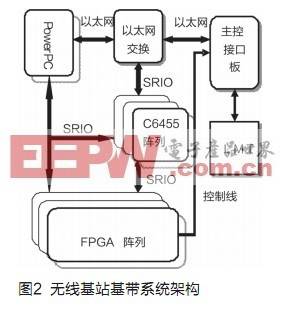
The wireless base station baseband system shown in FIG. 2 has extremely high flexibility and scalability. In this architecture, the task sub-tools of each processor have great flexibility. Because the architecture is no longer closely related to computing, traffic and processing power can be transferred from one device to another during runtime. The architecture is also scalable, helping to meet the increase and decrease in the number of endpoints required by specific applications in terms of performance and cost. For example, the DSP model and the number of DSPs can be easily changed so that the same design can be matched to the design requirements from microcells to large base stations. To reduce costs while meeting higher performance and bandwidth, the key is to adopt a modular and standards-based architecture. Building a next-generation baseband card and a structured architecture based on a serial RapidIO interface that connects multiple DSPs, FPGAs, and ASICs has many advantages.
Application of system in WiMAX BBU
· WiMAX BBU system architecture
Figure 3 is based on the WiMAX BBU system of Figure 2, the system hardware includes a PPC processor MPC8548, two DSP processors (TI's C6455) and three Xilinx FPGA V5LX110. SRIO port is used for communication between FPGA and DSP, PCI interface and SRIO are used for communication between DSP and PPC, and PCI-like interface is used for communication between FPGA. The SRIO interface is used for communication between DSP1 and DSP2.
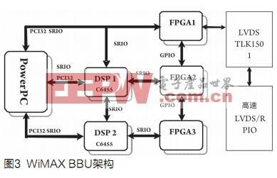
In this system, PowerPC and PCI32 of DSPC6455 are also interconnected, which facilitates downloading of programs in boot mode. FPGA1 mainly implements IFFT and PAPR algorithms; FPGA2 mainly implements RANGING and FFT algorithms; DSP1 mainly implements channel coding, modulation, space-time coding and subcarrier mapping; DSP2 mainly implements channel decoding, demodulation, channel estimation and subcarrier demapping. FPGA3 mainly realizes the decoding of TURBO. In addition, the MIMO uplink algorithm will be coordinated on DSP2, FPGA2, and DSP1.
·Test Results
In 4x mode, test the communication rate and error rate between DSP1 and DSP2.
Test plan: DSP1 is the master, DSP2 is the slave. The host sends data to the slave. In I / O mode, after the data is sent, the host sends doorbell to inform the slave and reads back whether the data received by DSP2 compares the data. In message mode, after the data link is sent, the hardware will generate an interrupt and enter In the interrupt service program, the receiving end automatically generates an interrupt after receiving the data link, and only needs to record the number of interrupts to judge whether the data is transmitted normally.
Select 3.125G baud rate for 1x mode communication. The test results are shown in Table 1. The results show that the high transmission performance of SRIO can meet the WiMAX baseband processing requirements and verify the feasibility and reliability of the WiMAX BBU system architecture proposed in this paper.
Conclusion
The wireless base station baseband system architecture proposed in this paper has the characteristics of high calculation rate, high bandwidth, feasibility and scalability. This system architecture has been actually applied to the WiMAX BBU system, and can also be used in a variety of wireless signal processing modules, such as radar interference systems. The task division of each processor is different in different embedded systems, and the implementation of SRIO technology also has great flexibility. For example: Direct I / O logic mode or message mode can be used to communicate.
Ultra HD fine pixel pitch brings video content to life.
Flicker free broadcast with exact full HD and 4K picture.
Sharp color & brightness uniformity.
Ultra-high dynamic contrast and high-quality display, ultra-high-definition perfect picture quality, bring you unprecedented visual enjoyment.
Easily attract attention, greatly enhance the value of advertising.
HD LED Screen with the high-precision cast aluminum material, perfect splicing without gaps. Fast locking makes installation and removal extremely easy.
High-quality aviation plugs ensure reliability.
Seamless splicing and installation type to assemble screen freely.
Patented connecting piece, and hang pin rotating at 120 degree to lock the case, and gap adjustable to ensure the seamless screen, and rapid installation and removal supported. Only 1/4 of installation time compares with traditional structure.
HD LED Screen with both vertical and horizontal large viewing angle are 140, broadcast-level color gamut, CT and brightness adjustable, more appropiate for long-time watching.
Support front service, modules can be taken out without opening the back door,power suppliers are fixed without screws.
Smooth display image is realized shooting with 3840HZ refresh rate, even under 1/2000 shutter professional camera shooting, fully meeting the demand of live feed switching.
It can be installed without taking the space for maintenance channel into consideration, thus improving your work efficiency.


Uhd Led Display,Uhd Led Screen,Uhd Led Backlight Display,Uhd Led Home Theater Display
Shenzhen Bako Vision Technology Co., Ltd. , http://www.rentalleddisplays.com