In the UAV flight control system , the flight controller is its core component, which is responsible for the acquisition of the flight control system signals, the calculation of the control law, the attitude and speed of the aircraft, and the communication with the ground equipment. With the increasing application of drones, the tasks it performs are becoming more and more complex, and the mobility requirements of drones are becoming higher and higher, which requires the control core of drones to be highly integrated. And the direction of miniaturization.
This paper takes the 586-Engine embedded chip as the core, designs the flight controller of a certain type of UAV, introduces the hardware structure and corresponding software flow of the system in detail, and gives the simulation experiment results.
The 586-Engine is TERN's AMD Elan SC520 processor-based micro-control module with high reliability, compact structure and low power consumption. It also has powerful debugging software. The main parameters of the 586-Engine are as follows:
(1) The CPU is a 32-bit AMD Elan SC520 with a frequency of 133 MHz;
(2) A high-performance floating-point arithmetic unit that supports complex operations such as sine, tangent, and logarithm, and is ideal for applications that require complex operations.
(3) 512KB SRAM, 512KB Flash, 114 bytes internal RAM;
(4) Support 15 external interrupts. There are 7 timers, including a programmable internal timer that provides three 16-bit internal timers and three 16-bit GP timers, plus a software timer. These timers support the timing and counting of external events. The software timer provides a microsecond hardware time base.
(5) Provide 32 programmable I/Os and 2 UARTs. A total of 19 12-bit A/D inputs, including 11 ADC serial inputs and 8 parallel ADCs with a conversion frequency of 300kHz; 6 D/A outputs including 2 serial output DACs and 4 output parallel 12-bit DACs The conversion frequency is 200 kHz.
(6) The working temperature is -40 ° C ~ 80 ° C, the size is 91.4 mm & TImes; 58.4 mm & TImes; 7.6 mm.
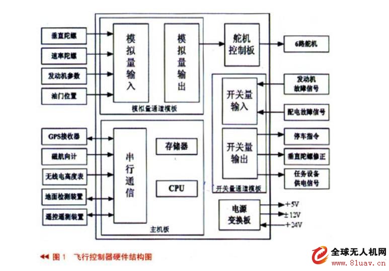
This type of drone is a medium-sized wheeled drone that provides communication relay for the naval field forces. Its flight controller is a small boxed small airborne electronic device, which is composed of DC/DC DC power conversion board and computer. The main board, the analog channel board, the switch channel board and the servo control board are all connected, and all the templates are connected by the bus on the motherboard to reduce the size and improve the integration. The hardware structure of the flight controller is shown in Figure 1, and the physical diagram is shown in Figure 2.
The following describes in detail the data acquisition, information transmission, and control output of the flight controller.
(1) Serial port expansion
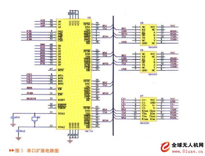
As can be seen from Fig. 1, the flight controller needs to communicate with GPS, magnetic heading meter and radio altimeter, and requires a total of five serial ports. The 586-Engine motherboard only provides two serial ports for ground detection and measurement and control stations, so serial port expansion is required. The serial port expansion circuit is shown in Figure 3.
The serial port expansion circuit uses TL16C754 four-channel UART parallel-serial conversion device to convert 8-bit parallel data into 4 serial outputs, plus MAX202 and MAX489 level conversion chips, and expands 2 RS232 serial ports and 2 RS422 serial ports. Meet the hardware requirements of the flight controller.
(2) D/A conversion
This type of UAV uses an analog servo, which requires a total of 6 D/A channels to generate a PWM signal to drive the servo. The 586-Engine mainboard provides a total of 8 D/A, of which 4 12-bit parallel D/A (DA7625) control the elevator, left and right aileron servos and rudder, 2 12-bit serial D/A (LTC1446) Control the front wheel servo and throttle servo. Since the output voltage range of the DA7625 is 0~2.5V, the LTC1446 output voltage range is 0~4.096V, and the servo operating voltage is -10~10V, so the signal needs to be amplified and level shifted. The D/A level shifting circuit is shown in Figure 4.
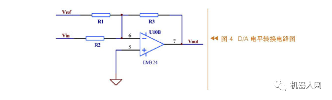
As can be seen from the figure, the D/A level shifting principle uses an adding circuit at the input end of the op amp to add the input signal to the reference level to obtain a voltage range suitable for sampling. The relationship between the input level and the output level is .
(3) A/D acquisition
The 19-channel 12-bit A/D interface on the 586-Engine main board fully meets the requirements of the flight control system channel number and conversion accuracy. These A/D interfaces respectively collect the data of the barometric altimeter, the UAV airborne voltage, Engine speed and temperature, throttle opening, etc. These signals are sent to the ground measurement and control computer, which provides the basis for the operator to monitor the working status of the drone.
(4) I/O control
The 586-Engine mainboard provides 32 16-bit programmable digital I/O ports for collecting engine start signals, umbrella cabin open signals, etc., and outputting switch signals to control other equipment to control the drone take-off and recycling process.
(5) Power module
The power module circuit of the flight controller provides a clean and stable supply voltage to the flight controller to ensure that the flight controller is working properly. The design of the power module circuit directly affects the stability and reliability of the flight controller operation. Because of the certain size requirements and the reliability and cost, this type of drone is designed with a mature standard module power supply and can be operated with a small number of external devices. The flight controller power supply module circuit is shown in Figure 5.
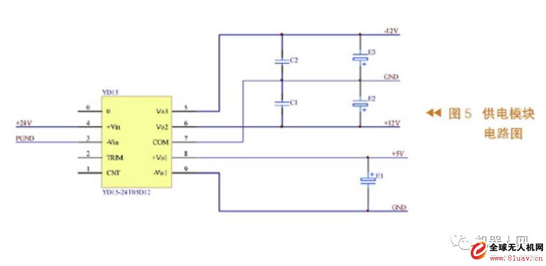
Among them, 24T05D12 module power supply is used as the main chip of the power supply circuit, the power is 30W, the input voltage range is 18V~36V, and there are three power supply outputs: +5V and ±12V to supply power to the onboard sensor and servo.
Control software design
Flight control software development environment
The development environment used by the 586-Engine microprocessor Paradigm C/C++ Professional is an integrated development environment for developing embedded system applications by Devtools in the United States. It supports embedded X86 systems, including an integrated development environment for X86. It includes compile, assemble, link, locate, and debug functions. It can edit embedded C/C++ code and support embedded X86 development systems in real mode, extended mode, and protected mode.
The flight control software development process is that the user compiles the program in the development environment, loads the program into the flight controller through the serial port, and can debug on the PC, which is its outstanding advantage. In addition, TERN provides the underlying operating procedures to facilitate software development.
Flight control software design
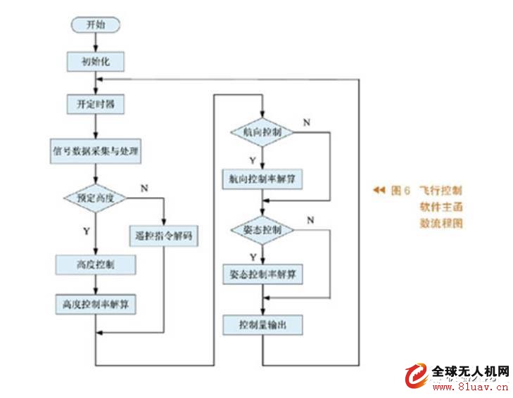
The airborne flight control software is generally divided into three major modules: initialization module, timing processing module and serial interrupt processing module.
The functions of each module are as follows:
(1) Initialization module: Mainly complete the initialization of the system, including A/D card initialization, DIO port initialization, serial port initialization, sensor initialization and parameter setting.
(2) Timing processing module: mainly completes time-related periodic tasks, including sensor signal acquisition, flight mode management, navigation calculation, flight control law calculation and actuator control.
(3) Serial interrupt processing module: complete the reception of remote command, magnetic heading meter and radio altimeter data reception.
The main function flow of the flight control software is shown in Figure 6.
Semi-physical simulation experiment
In the semi-physical simulation test, the control signal of the flight control computer passes the D/A conversion, and is amplified by the servo control driver to drive the actuator of the drone, that is, the electric servo servo, and then the simulation computer collects the electric servo through the A/D channel. The displacement signal of the steering gear, and the output control command (three-axis attitude angle) controls the three-axis flight simulation turntable, and simulates the attitude angle and attitude angular velocity of the drone. The onboard sensors feed these signals back to the flight controller to form a closed loop system that performs various missions. The simulation test can verify the safety and reliability of the flight control system and lay the foundation for the successful release of the drone. The results of the semi-physical simulation experiment are shown in Fig. 7.
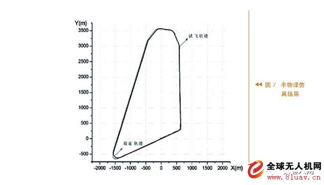
It can be seen from the figure that the drone can basically fly along a given route. After cutting into a straight segment or a circular segment, the side offset is small, and there is a certain overshoot at the turn. Overall, the control effect Better, after analysis, it is considered that the flight of the UAV is basically meeting the requirements of the demand side.
summary
The use of the 586-Engine embedded chip reduces the size and weight of the flight controller, and achieves the design goal of miniaturization and high integration of the flight controller; the self-designed serial port expansion circuit and the steering gear control board reduce the development. The cost meets the requirements of the project demand side. It is foreseeable that the unique features of the 586-Engine and the high cost performance will be widely used in the field of UAV flight control.
We provide wire harness manufacturing services for cable harnesses and built-to-print cables used in many industries, such as computer, game machine, POS machine, ATM , audio/video, electro-mechanical, data communications, telecommunications, medical, etc.
Related Products:speaker cable,customized cable assemblies,electrical cable assemblies.
We have developed a tradition of high-tech engineering, prototyping, and quality custom cable manufacturing at very competitive pricing. Also with professional flow chart (wire cutting-stripping-copper twisting-crimping-crimping 100% inspection-soldering-molding-asssembling-testing-FQC100% -OQC1-OQC2) , which can help us support customers with stable quality.
Custom Wire Harness Assembly
- Electrified dimensional build boards with 100% continuity test
- Capabilities to test for fuse,diode,resistor, and relay presence
- Mating test fixtures for lower production wire harnesses
- Ability to free hand build harnesses for prototypes and design validation
- Separate layout boards for addition of fir tree clips, rosebuds, clamps,and labels after coverings added
- Capabilities to add board interlocks and test markings to harness as needed
Speaker Cable,Straight Bnc Cable Assembly,Idc Red Custom Cable Assembly,Customized Cable Assemblies,EV Cable Assemblies,Cable Assembly,Custom Cable,Customized Cable Assemblies
ETOP WIREHARNESS LIMITED , https://www.wireharness-assembling.com