"We chose NI hardware and software development systems to reduce system development time, ensure system reliability, simplify the implementation of automated test solutions, and maintain and repair."
This article refers to the address: http://
A high-voltage battery model, simulated high-voltage current sensor and temperature sensor, and simulated high-voltage battery faults create a hardware-in-the-loop system for quality diagnostics for the battery management system (BMS) ECU.
We use the HIL system to test our complex real-time systems. This technology provides a platform to effectively check the control state of test hosts that require dynamic models.
System Overview
We use the BMS HIL system to test high voltage batteries for electric or hybrid vehicles to evaluate the control logic and fault diagnostics of the BMS. We created a battery model using Simulink and then applied the battery model to the development platform using the LabVIEW Simulation Interface Toolkit. We also use NI PXI systems to ensure efficient and reliable operation of the system.
The BMS HIL system enables quality diagnostics in a variety of test cases. By writing an automated test scenario, we reproduce all possible test cases for the battery system and use NI TestStand to organize and manage individual case scenarios.
We use LabVIEW to quickly deploy systems that use NI PXI to quickly generate and acquire signals that accurately reproduce battery pack voltage changes, including current and temperature changes in the BMS.
In addition, by using NI TestStand, we use BMS performance evaluation test cases to implement a simplified automated test solution.
Advantages of using NI products
We chose the NI hardware and software development platform to reduce system development time, ensure system reliability, streamline the implementation of automated test solutions, and simplify system maintenance and repair processes. At the same time, NI products are also compatible with Simulink.
System hardware configuration
The BMS HIL system hardware includes a computer that installs LabVIEW and controls the entire system, a real-time NI PXI hardware platform that captures and provides signal output, a battery pack voltage generator that mimics the battery pack, and a set of signal conditioning units. In addition, the system includes a fault injection module that simulates various test errors, a power supply that supplies power to the BMS ECU, and an interface box that connects the HIL simulation system to the ECU.
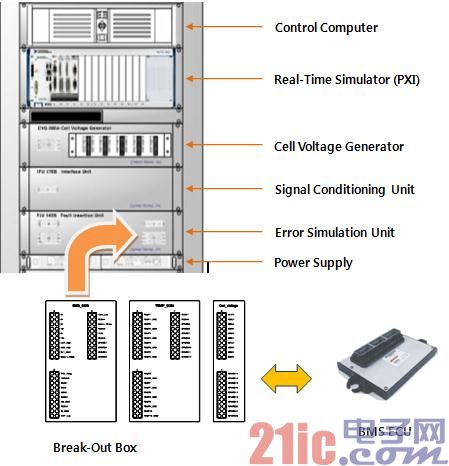
Figure 1: BMS HIL hardware-in-the-loop system hardware configuration
System software configuration
The BMS HIL system software is mainly divided into two different subsystems. We use the first subsystem to manually generate errors and multiple configurations to check ECU performance; the other is an automated system that uses NI TestStand to pre-set various errors and then automatically check ECU performance.
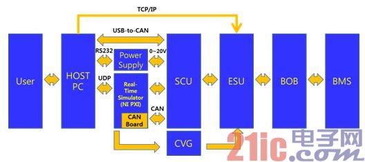
Figure 2: BMS system signal flow chart
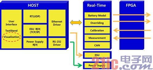
Figure 3: BMS HIL simulation system software configuration diagram
When the host computer receives a control command request from the user, the PXI real-time controller specifies the rules for real-time signal acquisition or output. The specified tasks are completed in real time with a field programmable gate array (FPGA).
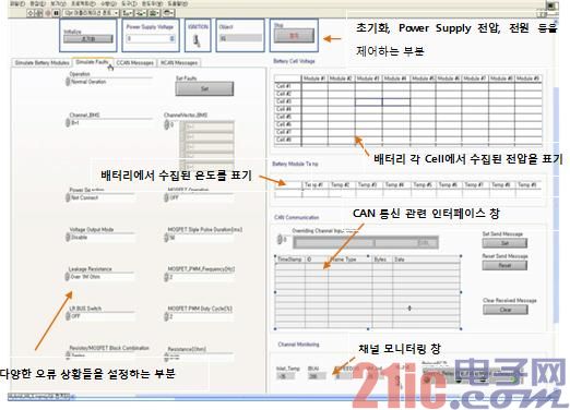
Figure 4 BMS HIL system user interface configuration
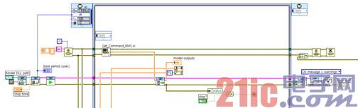
Figure 5 Battery model using the LabVIEW Simulation Interface Toolkit
The battery cell voltage, battery temperature, and battery current generated from the battery model can all be simulated using an FPGA. Because FPGAs offer high speed performance, we can increase the response speed of the current generated from each battery pack.
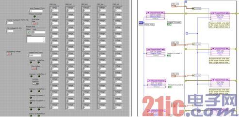
Figure 6 Using the FPGA to generate battery cell voltage output from the battery model
Test plan implementation
By using NI TestStand (see Figure 7), we can simplify the automated test scenario by sequentially arranging various error conditions and corresponding configurations that occur in the battery system.
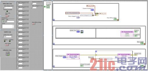
Figure 7: Using the FPGA to generate the specified temperature and current output
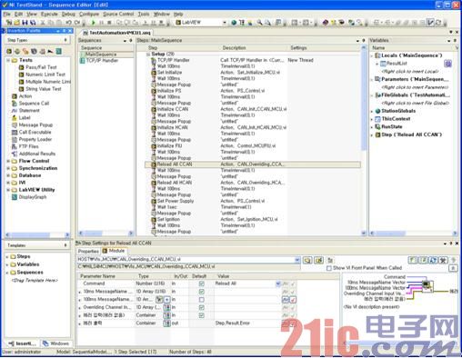
Figure 8 Applying NI TestStand to perform an automated test scenario
in conclusion
Using our BMS HIL hardware-in-the-loop test system can reduce the costs and risks associated with battery testing of electric or hybrid vehicles. The system also provides a test environment that includes battery cell voltage, current, and temperature, which are difficult to set together. In addition, applying NI products can increase hardware reliability and reduce system development time.
Using the LabVIEW and LabVIEW Simulation Interface Toolkit, we quickly implemented the user interface and applied the battery model in Simulink. With NI TestStand, we can configure many test cases to produce a readable BMS performance assessment and a simplified automated test solution.
1 Hour Fireproof Safes
1 Hour Fireproof Safes are safes that can resist fire attack for 1 hour.
Details:
Special fireproof material stuffing which resist damage;
Seamless molding case;
Heavy duty style doors and hinges;
Anti-drilling, anti-burglar and anti-force;
Yongfa patent: dual system protection;
Fire proof for 1 hour and it can ensure an inner temperature to be less than 177°C(350°F), while exposed to 927°C(1700°F) flames;
Strong hinges and door-bolts;
UL certification passed.
1 Hour Fireproof Safe ,Mechanical Fireproof Safe,Fireproof Gun Safe,High End Fireproof Gun Safe
YONGFA INTELLIGENT TECHNOLOGY SECURITY CO., LTD. , http://www.yongfa-safe.com