In the motor controller manufacturer of pure electric vehicle motor drive system, the output current is not only related to the input voltage, but also related to the system load. Therefore, it is necessary to adopt the closed-loop PWM method. The current PWM method uses a closed-loop control algorithm to perform PWM control on the inverter based on the feedback information of the current in the sensor. When using the current PWM method, it is necessary to compare the three-phase current measured by the sensor with the three reference current signals generated by the system external loop controller. The PWM algorithm outputs a corresponding strobe signal based on the error between the measurement signal and the reference signal. There are also many PWM methods based on current control, both of which are relatively simple and very complex.
These methods include hysteresis current control, ramp intercept control, and predictive current control. The predictive current control method is more complicated, and it performs current prediction based on the load. Two relatively simple current control methods, hysteresis current control method and ramp intersection control method are briefly introduced below.
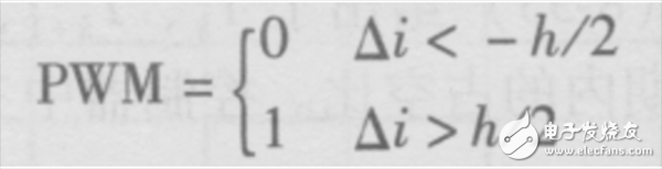
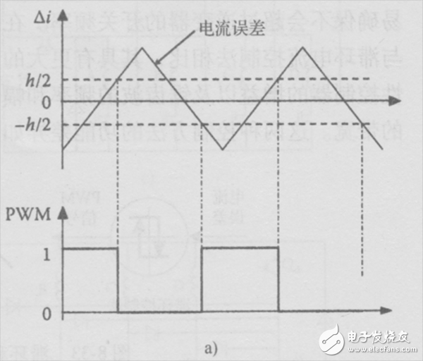
Hysteresis current controlIn the hysteresis current control method, the error between the measured current and the reference current is compared with the hysteresis band, which is shown in Figure 8-32a. If the current error is within the hysteresis band, the PWM output remains unchanged. If the current error exceeds the hysteresis band, the PWM will output a reverse effect, varying in di/dt gradient. From a mathematical point of view, the output of the PWM can be expressed as
Current control method for pure electric vehicle motor drive system
If the PWM output signal is “0â€, it means to disconnect the voltage source of the control phase to attenuate the current; if the PWM output signal is “1â€, it means to close the voltage source of the control phase to make the current larger. The voltage forces the current to change so that it remains in hysteresis.
The advantage of this control method is that the current error is always kept within a certain bandwidth, which is known to the user in advance. In the hysteresis current control method, the switching frequency is unknown, which makes designing the filter more difficult. The switching frequency should be carefully monitored to avoid exceeding the limits of the inverter. In actual use, the upper limit of the switching frequency is usually set to avoid exceeding the maximum limit of the inverter switching frequency. The hysteresis bandwidth is usually designed based on the switching frequency of the power device. If the hysteresis bandwidth is chosen to be very narrow, the switching frequency needs to be very high and cannot exceed the maximum switching frequency of the power device. On the other hand, if the bandwidth is wider, the current error will be very large.
Hysteresis current control can be applied to three-phase PWM inverters, each with a PWM controller. If the actual current is half the hysteresis bandwidth of the reference current, the low voltage side of the bridge inverter will close to reduce the phase current. There is also a difficulty in three-phase hysteresis control. According to hysteresis control, there may be conflicts in the requirements of the phase of each phase. When considering the relationship between the hysteresis control of the three-phase system and the hysteresis control of each phase independent, the difficulty is even greater. The result of this difficulty is that the current may not be able to remain within the hysteresis bandwidth.
For example, if there is an instruction that requires a phase current increase, the low voltage terminal of phase b or phase c needs to be used as the loop, and if the high voltage terminal of phase b or phase c is closing at this time, the phase a current cannot follow the command. The current increases. In this case, the error of the phase a current may exceed the bandwidth of the hysteresis loop. Using the dq transformation theory, the three-phase current can be first converted to a two-phase dq current, and then hysteresis current control is used in the dq reference frame.
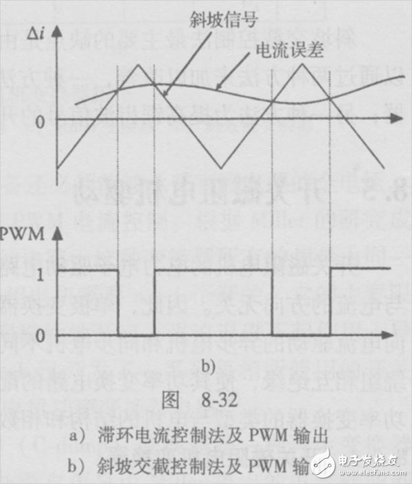
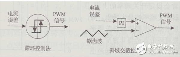
Slope crossing control methodThere is another way to control the stator current. The controller of this method is based on a fixed frequency ramp signal and the ramp signal determines the switching frequency. The current error is first passed to a linear controller, and the typical linear controller is a proportional integral (PI) type. The output of the linear controller is compared to a high frequency sawtooth triangular wave signal and then the PWM switching signal is output. If the error signal is higher than the triangular wave signal, the PWM output signal is "1", otherwise the output signal is "0", and the control process is as shown in Figure b. In order to reduce the current error, the stator voltage is constantly changing. Use the same three controllers in a three-phase system.
The ramp crossover control method has a fixed switching frequency whose frequency is determined by the frequency of the sawtooth wave, so that it is easy to ensure that the switching frequency of the inverter is not exceeded. Many parameters can be adjusted in the slope intercept control method, so it has more flexibility than the hysteresis current control method. The control parameters of the ramp intersection control method include the gain of the linear controller and the frequency and amplitude of the sawtooth wave, while the control parameters of the hysteresis current control method are only the hysteresis bandwidth. The functional differences between the two control methods are shown in the figure.
The main disadvantage of the ramp intercept control method is that the response time is lengthened due to the transmission delay. This situation can be improved in two ways, one is to replace the PI controller with a high gain proportional controller; the other is to increase the switching frequency of the sawtooth signal.
Automatic Tunnel Cleaning Vehicle,Tsv Tunnel Cleaning Vehicle,Long Tunnel Cleaning Vehicle,Powerful Vacuum Cleaning Vehicle
CRRC SHANDONG CO., LTD. , https://www.crrcsd.com