The Prius is a hybrid car from Toyota Motor Corporation of Japan. This article will disassemble and analyze the instrument panel display system and the anti-skid control module of the electronic part of the hybrid vehicle.
This article refers to the address: http://
While many vehicle status information and vehicle control functions are displayed and implemented through the central touch screen panel, critical information is provided by a dedicated display system that is visible at a glance behind the steering wheel. The Dashboard Module (DM) provides most read-only information, such as speed, oil level, gear position, odometer/km, etc., digitally and an icon-based vacuum fluorescent display (VFD) panel. The emergence of VFD technology has been around for some years, and the PFD of the Prius may come from Futaba or Noritake. Toyota appreciates the digital reading method. It has not been used in the past few years to popularize the analog pointer table that has recently become popular again.
For VFD, in automotive applications, glare of external sunlight reduces resolution, so readability and contrast are more important. To further improve visibility, the driver actually sees a double-reflected VFD image instead of a direct image of the panel. The two mirrors below the dashboard direct the output of the VFD to the light path indicated to the driver, which filters out the scattered light from the VFD module and improves the quality of the driver's look and feel experience. Although the current required by the VFD is not particularly high, it requires high voltage. In addition, an Oki Semiconductor MSC1162A 40-bit VFD display driver converts the output from the Fujitsu MB90583C 16-bit microcontroller to the appropriate level to Fluorescence is obtained in the drive electrode in the vacuum chamber sealed by the panel.
A 5V regulator, mysterious Toshiba chip (clock?) and a serial EEPROM are the main ICs soldered to the dashboard. In addition to display control, Fujitsu's microprocessors form the communication interface that supports the gear position sensor and the engine control module. It is unclear whether the speed and mileage information is calculated and stored in the DM, or is the DM only responsible for information display, and the display data comes from other modules of the Prius?
There are two white modules that are also connected to the DM, and they are equally unexpected. When opened, the inside is an oil-immersed V-shaped pendulum with a magnet at the swing arm end that swings over a Hall effect sensor. My first thought was that it might constitute a yaw sensor that would be mentioned in the Slip Control Module (SCM), but its slow damping effect is unlikely. In view of its construction, its more likely use is in conjunction with the DM circuit, and its orthogonal arrangement during installation acts as a tilt sensor to compensate for the displayed oil level. The sensor can be used to recalibrate the displayed oil level when the vehicle is parked at an angle such that one or both of the axles of the vehicle are angled, so that even if the oil in the tank is not within the sensing range of the tank's built-in fuel gauge, it is ensured Accurate oil level readings. Once again, due to the complex design of Prius, it is sometimes difficult to find out the function of any module in the car.
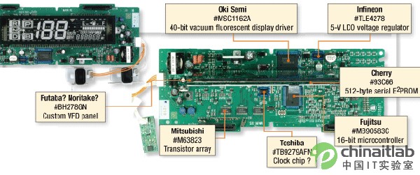
Figure 1: For the dashboard, the Toyota Prius seems to appreciate the digital reading mode and does not follow the analog pointer table.
Analog custom circuits are critical to SCM
We purchased a new fully equipped Prius to decipher how its electronic system was implemented. Underneath the cover is the details of the power control system, power transmission/recovery electronics and infotainment/navigation system of the gas/electric hybrid vehicle. Now we will analyze its anti-skid control module (SCM)
SCM is used to control and correct traction losses. It works in conjunction with the Prius brake control system (which drives hydraulic friction braking and optimizes the use of regenerative braking as a fuel-saving measure), and the SCM controls the conditions under which each wheel should be acted upon. The module communicates with the drive loop control electronics to adjust the power delivered. The basic inputs of the SCM include wheel speed sensors on each wheel and brake fluid pressure sensors on each wheel brake hub. Other inputs to the SCM have yaw, deceleration, and steering angle sensors.
To a certain extent, most of us are over-enthusiastic about accelerators that compromise the friction of slippery roads. The Prius SCM compares the speed of the front (drive) wheel with the rear (slave) wheel. This allows it to detect the simple reciprocation of the tire under a given force to achieve a consistent speed target between the front and rear wheels.
Another task of the SCM is to handle and prevent tire locks in emergency braking situations. At present, the anti-lock braking (ABS) system has actually become the standard for automobiles, and SCM has also incorporated several tasks of ABS into its own jurisdiction. The SCM monitors the speed of the wheels to ensure that each wheel stops at the same rate. When the SCM finds that one wheel (or several wheels) is locked, it sends an instruction to the brake control system to suspend further braking.
To minimize side slip and maximize brake performance.
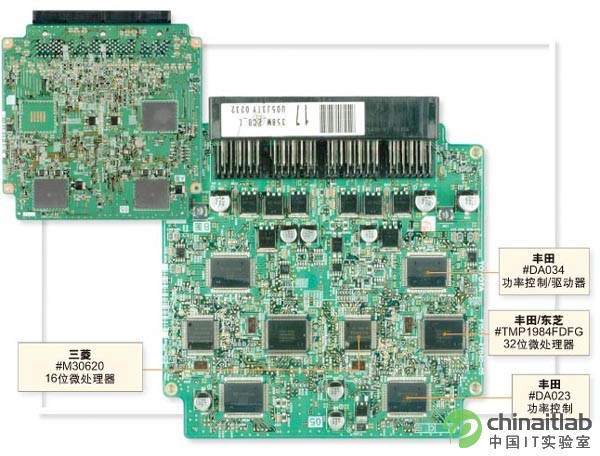
Figure 2: The anti-skid control module communicates with the drive loop control electronics to adjust the power delivered. In the SCM function, overall friction and stability control is its most important task. The SCM will work when there may be insufficient steering control (when the steering action is taken, the car will still "forward") or the steering control force is too large (the car will turn backwards). By monitoring the steering wheel angle, relative wheel speed, yaw and possible side g forces, the SCM can determine if the front wheel friction loss (not enough steering force) or the rear wheel friction loss (too much steering force) is about to be turned when steering occur. In addition, the SCM, along with the brake system, carefully guides the applied braking force to the various wheels.
As with most of the key electronic systems found in the Prius spin-off, the SCM implementation is still conservative. There is a full piece of cast iron under the cover, and under the dashboard there is a PCB with a sealed auxiliary IC and a large number of devices. Based on a diagonal safety control concept such as front right/rear left and front left/back right wheels, I suspect that the SCM is correspondingly implemented in a center-symmetric manner. With this redundant implementation, even with partial failure, one front wheel and one rear wheel are available for use in the control loop driven by the SCM.
Since the input signal modulation and the drive output of the brake transmission are not essentially digital tasks, the analog circuit plays a key role in the SCM implementation. The SCM's computing hub is powered by a Toshiba TMP1984FDFG 32-bit microprocessor with the Toyota logo and a Mitsubishi M30620 16-bit microprocessor, which is a controller with a built-in mask memory. It was 1995. This again shows that in the design of the Prius, conservative is the guiding principle. However, in addition to data processing, Toyota has adopted a custom strategy for its mixed-signal interface circuits. Simply from the chip itself, the Toyota DA023 and DA034 are analog control or modulation devices. We did not find a commercial foundry mark on the market, but there is a small Toyota logo under the device label.
Although the number of devices behind the PCB is small, the large control current required for analog devices requires heat to be considered. The DA023 and DA034, which are symmetrically distributed on the left and right sides, use a heat-dissipating pad attached to the outer casing on the other side of the SCM board to dissipate the heat generated by the chip and keep the temperature of the module from being too high.
In short, Prius's complex stability control relies on conservative processor selection and well-crafted analog custom circuits.
Sumitomo Automotive Female Connector,Sumitomo Automotive Male Connector,Wire Connector
Wire Harness,Automotive Cnnectors Co., Ltd. , http://www.nswireharness.com