0 Introduction At present, digital video systems have been widely used in daily work and life, such as surveillance systems, video telephony, digital television, etc., and with the advancement of technology and the increasingly high demand for video image quality in work and life, processing The amount of data is getting larger and larger, which raises two new problems: on the one hand, the hardware requires faster processing, such as monitoring systems and video telephony systems require real-time; on the other hand, data storage is required. The media is larger and more portable. In order to realize the independent operation of the DSP (Digital Signal Processing) system, a large-capacity storage medium is required for storing video data. In this paper, TI's high-end multimedia processing chip DM642 is used as an image processing chip. Its powerful computing power, rich peripheral interface and complete programmability can be easily used to develop various image systems. The use of the CF card can make up for the fact that the onboard flash capacity is usually too small, and the data will be lost after the SDRAM is powered down. At the same time, the pin-type connection method adopted by the CF card has relatively high shock resistance and stability, and can better meet the requirements of portable devices. In the video codec aspect, the MPEG-2 algorithm provided by TI can basically meet the requirements of compression efficiency and quality.
This article refers to the address: http://
1 Introduction to CF Card The CF card is called Compact F1ash. It was first introduced by Sandisk in 1994 and has now become an industry standard. Its internal schematic is shown in Figure 1. The CF card consists of two basic parts: the control chip and the flash module. The control chip is used to connect to the host and control the transfer of data in the flash module, while the flash module is used to store information. The CF card is compatible with 3.3V and 5V operating voltages and supports multiple interface access modes. At present, the capacity of CF can be as high as 100GB, the mainstream capacity has reached 4GB, and the price has dropped to about tens of yuan, and the cost performance is very high.

2 DM642 and CF card interface design
2.1 Hardware Interface Design The CF card supports three basic working modes: PC Card Memory mode, PC Card I/0 mode, and True IDE mode. The pin functions corresponding to different modes are slightly different. In the design of this article, the PCCard Memory mode is used. Before inserting the CF card, ensure that the CF card slot/REG pin is high, so that the CF card can automatically enter the PC Card Memory mode. DSPs access the off-chip memory through the external memory interface EMIF (External Memory Interface). The EMIF of the DM642 has four spaces: CEO, CEl, CE2, and CE3, each with 256MB of addressing space. In the system design described in this document, the CE2 space is configured as the address space of the CF card for the CF card. According to the requirements of the Memory mode, the CE2 space is configured as an 8-bit asynchronous interface. In addition, a CPLD is specially equipped for the CF card. Read and write control, hardware connection as shown in Figure 2.

The pin connections are described as follows: The /REG signal is used to select whether to access the normal or attribute registers. Together with the address line A[3:0], the selection of the read and write registers is completed. /CDl and /CD2 are used to detect if there is a CF card in the slot. When the CF card is inserted into the slot, these pins will be pulled low. /CEl and /CE2 are used to select the data transfer width of the CF card. This design is 8-bit wide. To save IO port resources, /CDl, /CD2, /CEl, /CE2, and I/REG are all connected to the configured General Purpose IO (GPIO) port.
TEAl3 controls REG, TEAl2 controls CF of CF card, TEAl 1 controls CE2 of CF card, DSP_CE2 is the enable signal of CE2 space, ARE and IAWE are read and write signals of asynchronous interface, all are active low, they pass with DSP_CE2 The logic is ORed and connected to /0E and /WE of the CF card, so that after /CE2 is enabled, the CF card can be controlled to read and write.
The CF card has a 16-bit data bus, but can be flexibly configured to 8 or 16 bits according to the data width of the main controller. In this system, the lower 16-bit data bus D[15:0] of the DM642 and the data bus of the CF card are used. D[15:0] is connected. The CF card's 11-bit address bus takes the lower four bits A[3:0] to the DM642's TEA[6:3], the CF card's TEA[9:4] to ground, TEAl0 to the DM642's TEA7, CSEL to ground, IOWR IORD is pulled up to VCC, and other pins that are not used are grounded.
2.2 CF card software interface CF card read and write is based on the sector (sector), each sector is 512 bytes, each read and write one or more consecutive sectors. In this paper, the CF card is configured as PC Card Memory mode, and the register address mapping in this mode is shown in Table 1.
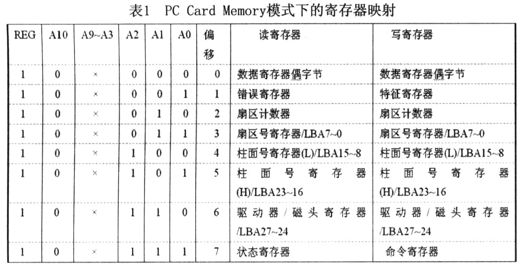
Register 0 is used to read and write data. Register 1 is an error register during read operations. It stores error information and is a feature register when written. Register 2 is used to store the number of read and write sectors. Registers 3~6 are used to store the address of the read/write sector. There are two ways to address the sector of a CF card: physical addressing (Cylinder/Head/Sector, CHS) and Logical Block Addressing (LBA). CHS is the address of the specific cylinder, head and sector corresponding to the sector, and the address of the LBA is logically continuous. The conversion relationship between the two addressing modes is: LBA address = (cylinder number × number of heads + Head number) × sector number + sector number one. This paper chooses the linear addressing mode of LBA.
Register 7 has a different meaning when reading and writing. The read operation is a status register that stores the status information of the CF card. When writing, it is a command register, which is used to set the command and complete the corresponding operation.
Before the CF card reads and writes the program, initialize the DSP and CF card, initialize the GPIO, set the CE2 space of the DM642 to an 8-bit asynchronous interface, configure /REG to a high level, and set the CF card to an 8-bit data interface.
When reading and writing sectors, first set the LBA address of the starting sector and the number of sectors to be read and written, and then set the command register. The read data is set to 20H, and the write data is set to 30H. After writing, Read the status register, the read and write operations can only be started when the status register is "58H", otherwise the status will continue to be queried. Since the data interface is 8 bits, it is necessary to read or write 512 data registers for one sector. After that, read the status register to see if it is "50H", and judge whether the CF card operation is completed. If it is completed, exit this operation, otherwise continue the query until it is completed.
The CF card writes a sector function part of the source code as follows:
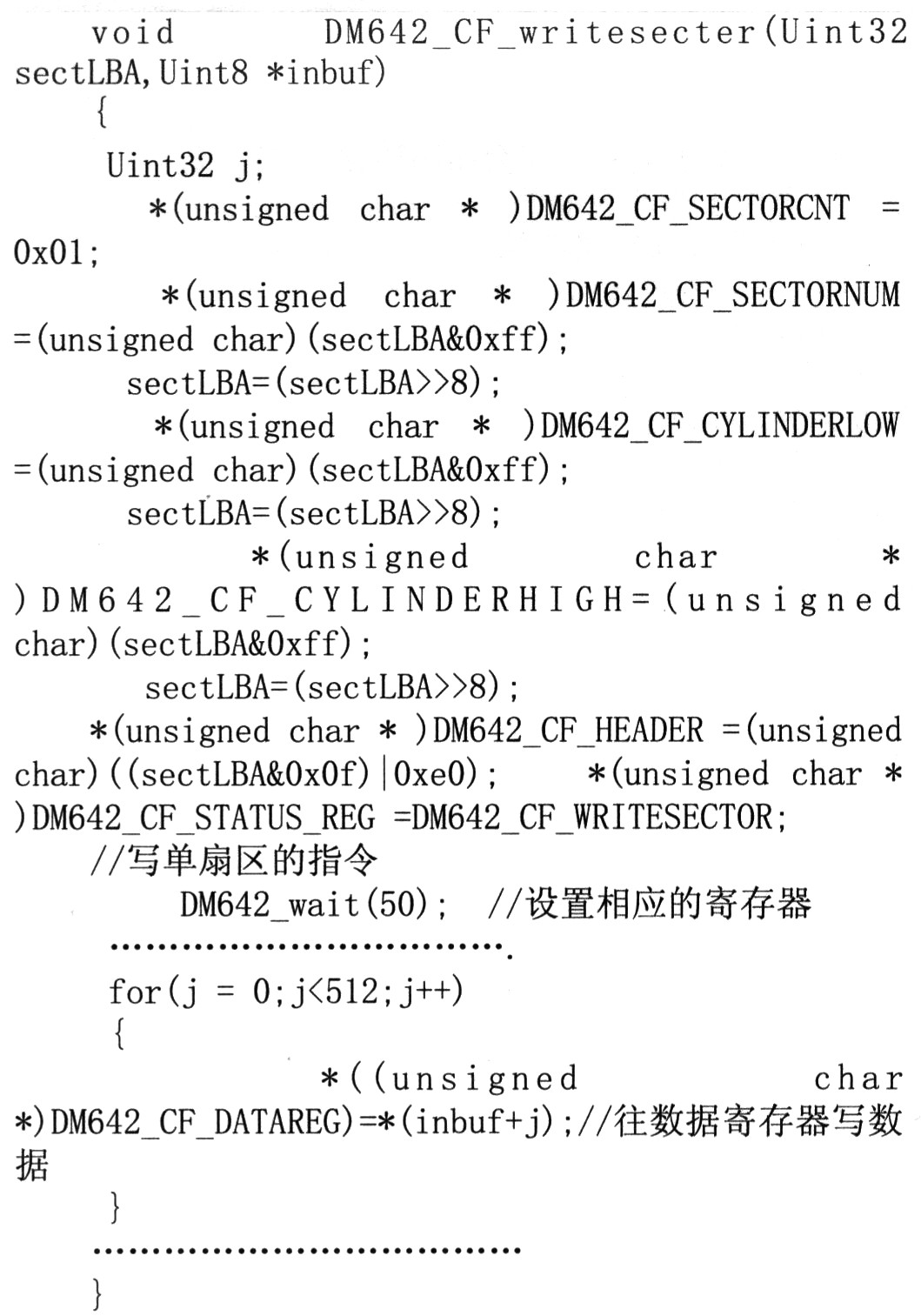
The method of reading and writing multiple sectors is similar. Set the number of sectors and the corresponding read and write commands. Generally speaking, setting the loop read and write directly is more efficient than calling the subroutine because it only needs to read. Write the start address of the sector once.
2.3 CF card memory space management The CF card in this system stores video data in mpeg2 format. Although the length of the video is uncertain, the sector address is 4 bytes when addressed by LBA. In this design, the storage space of the CF card can be allocated as follows: the first sector stores the index information of the video; and the image data is stored from the second sector.
The data format of the first sector of 512 bytes is as follows:

The total section is the total number of video data stored, initially 0; the current section is the number of the video to be operated, initially 1; addressl is the starting address of the first video, the initial value is 0x00000002, and Address2 is the starting address of the second piece of video data, the initial value is 0, and the subsequent data is set to 0 at initialization.
Every time the system starts, you need to read the information of the first sector first. The information read is placed in an infolba array with a width of 4 bytes. The video address to be read and written in each segment is calculated as follows: currentaddress =infolba[current section], correspondingly rewrite the first sector after the completion of the read and write operations, and update the index information, specifically the address of the total section, the current section and the next piece of video data.
From a practical point of view, the first sector can store the first address of about 125 segments of video, which can basically meet the requirements of use. According to the design addressl value is always Ox00000002, and the total section and Icurrent section have a specific size relationship, then the first three data of Infolba can be used as a check mark to detect whether the current CF card space allocation meets the requirements, if not met The request is initialized according to the initial value. In general, current section=totalsection+1, when the current section is less than or equal to total sectiOn, if the sector write operation is performed, the data information after infolba[current section] will be overwritten or the index information will be lost. Reuse of CF card memory space. In the system, the control signal is input through the external hardware control circuit, which can conveniently realize the functions of recording, playing, fast forward, fast rewind, pause, etc. It is obvious that the value of the current section can be changed on the CF card by fast forward and fast rewind. The video data is played or overwritten.
3 Conclusion This paper gives the software and hardware interfaces of CF card and DM642. The software project is integrated through CCS2.2 platform and RF5 framework, and the CF card is successfully applied to the portable digital video system based on DM642. After the program is programmed into the onboard flash, it can be powered on and started. Through many experiments and optimization of the program, the system works well, which shows that the solution successfully solves the real-time, large capacity and stability requirements of portable devices, and has broad application prospects.
Cardboard Dumpbin Display,Cardboard Dump Bins,Cardboard Dump Bin Displays Stand
Cardboard Floor Display,Cardboard Counter Display Co., Ltd. , http://www.chcosmeticdisplay.com