introduction
This article refers to the address: http://
The Consumer Council has conducted an investigation and analysis of the problems existing in the current freight industry. The valuables that consumers have entrusted to transport are seriously lost during the transportation process, resulting in an increasing amount of damage to consumers. Logistics companies often undertake the task of transporting valuables, and the loss of these valuables will lead to huge losses. Logistics companies use traditional GPS positioning technology to track valuables and reduce the chance of item loss. However, in complex geographical environments such as underducts or dense urban buildings, satellite signals are easily lost; and during the transportation of the entire item, valuables are not available in GPS containers when they are placed in metal containers of trucks or stored indoors. Satellite positioning signals make it difficult to effectively track and locate valuables. At the same time, in the traditional solution of the logistics company monitoring system, the GPS vehicle positioning service uses the GSM or CDMA mobile network short message as the communication medium, and the positioning and alarm information is sent to the end user through the mobile phone short message, which is inconvenient. The logistics company monitors, queries and manages the entire system in real time.
In order to meet the urgent needs of logistics companies to track and locate valuables, this paper proposes a set of solutions based on GPSOne technology. The solution can not only locate in real time and accurately in various environments, but also timely alarm through the Internet in the event of a theft. It is convenient for the logistics company to monitor, query and manage in real time, so as to prevent items from being lost more effectively and promptly investigate the responsibility. .
1 positioning system solution
DTGS-800 module positioning using CDMA is a good logistics tracking management solution. Based on GPSOne technology, this module can not only realize positioning, but also built-in TCP/IP protocol stack, which can easily connect to Inter-net to transmit data, which is convenient for logistics company to monitor and manage.
GPSOne is a hybrid positioning technology that combines A-GPS (Assisted Global Position System) with CDMA triangulation. The organic combination of the two makes the two positioning technologies complementary. In the suburbs and rural areas far away from the urban area, CDMA triangulation technology is less accurate due to the scarcity of wireless base stations, but the satellite signals in these places are strong, and the position information provided by A-GPS can be fully utilized to achieve accurate positioning; in the prosperous areas of the city, large Commercial buildings, office buildings and other high-rise buildings are densely populated or indoors, satellite signals are weak, A-GPS positioning is not allowed, but CD-MA base stations in these areas are dense, and AFLT (Advanced Forward Link Trilateration) can be used. The technology overcomes the shortcomings of the A-GPS positioning blind zone and implements precise positioning.
At the same time, the DTGS-800 module uses the machine card separation technology. As long as a R-UIM card is opened for Internet access and GPSOne positioning function, then the module can be plugged in to obtain Internet access and location services. The DTGS-800 module comes with a TCP/IP protocol stack. The module can automatically connect to the Internet using the TcP protocol wirelessly by simply giving the module a corresponding command. Before connecting, set the connected IP address and port number to the IP address and port number of the monitoring server, and you can implement Internet data transmission. The corresponding software is opened on the monitoring server to receive the information and then saved to the database. The GIS (Geographic Information System) can be used to track and query the location of the logistics vehicles and items in real time, which is convenient for the logistics company to monitor and manage in real time. The entire positioning system is shown in Figure 1.
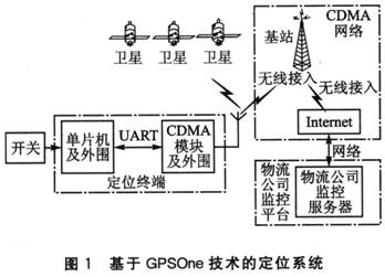
The positioning system includes four parts: positioning terminal, CDMA network, satellite system and logistics company monitoring platform. The positioning terminal acquires the current time, latitude and longitude information through the satellite or CD-MA base station, and then sends it to the Internet through the CDMA network, and the logistics company monitoring platform uses the software to receive corresponding information from the Internet. As long as the R-UIM card has the CD-MA's GPSOne positioning and Internet access function, the corresponding services for the CDMA network and the satellite system can be obtained. The process of data transmission can be regarded as transparent transmission, which can be regarded as data directly sent from the positioning terminal to the monitoring platform of the logistics company.
The entire positioning system works as follows: The DTGS-800 module, the travel switch, the antenna and other auxiliary circuits are packaged into a single unit to form a positioning terminal, which is fixed at the unpacking port of the storage item container. During the transportation process, when the container is sealed and transported normally, the positioning terminal can periodically send the latitude, longitude, time and other information to the monitoring platform; and when the container is abnormally opened, the travel switch is touched, and the positioning terminal can send the monitoring platform to the monitoring platform in time. Alarm information and positioning information. The logistics company receives this information through the monitoring platform and combines the logistics schedule to analyze the logistics situation at the time of the incident. It can judge whether an abnormality occurs and timely process it, so as to realize the real-time monitoring functions such as tracking, anti-theft, query and management of the logistics process.
2 system hardware design
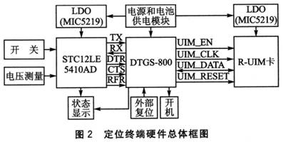
The overall block diagram of the positioning terminal hardware is shown in Figure 2.
2.1 System composition
The entire positioning terminal system includes a power supply and a battery power supply module, an MCU module and peripheral circuits, a DTGS-800 module, and peripheral circuits. The DTGS-800 with positioning function is controlled by a single chip microcomputer, and the communication between them is done through the serial port. Since the selected MCU and DTGS-800 are operating at their respective operating levels, they can be interconnected directly without the need for additional level shifting circuitry. The DTGS-800 uses a card separation technology to provide a connection interface to the R-UIM card.
2.2 System module design
2.2.1 Power and battery powered modules
The power supply section consists of two parts: dedicated battery power and automotive power. The entire terminal system uses a special battery power supply. When the transportation stroke is long and the battery power is insufficient, the system voltage detection circuit will issue an alarm, which can be converted into power supply by the vehicle power supply. The power supply section is described below in two aspects.
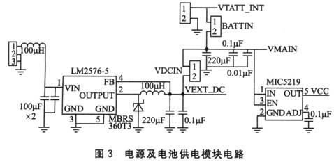
Specialized battery powered. There are two ways to power the DTGS-800: battery powered (VBATT_INT pin input) and external power supply (VEXT_DC pin input). When powered by battery, the supply voltage VBATT_INT is required to be in the range of +4. OV ± 10%. Therefore, a lithium polymer battery having a capacity of 10 Ah and an output voltage of 3.7 V was selected. Since the selected microcontroller is powered by 3.3 V, the battery needs to add an LDO (Low Dropout Linear Regulator) chip MIC5219 when supplying power to the microcontroller. The minimum differential voltage can reach 0.3 V, which meets the design requirements.
Car power supply. At present, most of the batteries used in automobiles are lead-acid batteries, the batteries for small cars are generally 12 V, and the batteries for large and medium-sized cars (diesel engines) are 24 V. When the DTGS-800 starts up, it must first initialize the system and find the network. The power consumption is high, about 300~500 mA. After stabilization, the maximum power consumption (in the case of calling or surfing, positioning) is about 300 mA. There must be a margin in the design, so the power supply requires a stable DC supply of 4.5 to 5 V, 1 A in the case of external power supply (VEXT_DC), up to 5.5 V. Considering that the voltage difference is large and the output current is required to be greater than 1 A, a DC-DC (switching power supply) chip LM2576-5 with an output voltage of 5 V and an output current of up to 3 A is selected. Compared with the disadvantages of high power consumption and low conversion efficiency when the LDO voltage difference is large, the DC-DC power supply chip has high conversion efficiency, and the power consumption is not too large when the voltage difference is large. The power and battery power module circuit is shown in Figure 3.
2.2.2 MCU module and peripheral circuits
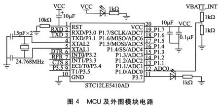
The MCU selects the STC12LE5410AD from Acer Technologies, which operates at 3.3 V, making it easy to operate with selected system power. This is a single-chip chip with A/D conversion, which has superior anti-interference characteristics and ultra-low power consumption. The current is only 4~7mA during normal operation and <1 mA when idle. Its duty cycle is only one clock cycle, which can greatly reduce the frequency of the crystal used, thus reducing EMI (Elec-tromagnetic InteRFerence). STC12LE5410AD features fewer pins, smaller size, lower price, and ease of use, which reduces development costs and shortens development cycles.
The MCU peripheral circuit includes a crystal oscillator circuit, a reset circuit, a switch detection circuit, and a voltage measuring portion. The switch detection circuit is used to detect the action of the travel switch. The voltage measurement part uses the A/D conversion function of the single chip microcomputer to measure the battery voltage supplied by the DTGS-800. When the battery voltage is detected to be insufficient, an alarm will be issued. Switch to the car power supply. The MCU and peripheral module circuits are shown in Figure 4.
2.2.3 DTGS-800 module and peripheral circuits
The CDMA module uses the DTGS-800 from Qualcomm's integrated MSM6050 chipset with GPSOne positioning. This module interface has a total of 100 pins, which can provide functions such as telephone, SMS, audio, fax, positioning, Internet access and data transmission. It also provides a variety of user interfaces, such as serial port, keyboard and LCD interface. Users can conveniently follow the needs. Develop.
The DTGS-800 and the MCU interface use a 3-wire (TXD, RXD, GND) serial port. The AT command can be used to implement functions such as making calls, sending text messages, and positioning. However, in the case of Internet access and data transmission, a serial port flow control signal is required. Such as RTS, CTS and DTR, etc.). The RTS sends a signal for the request; the CTS clears the transmit signal and acts as a flow control; the DTR prepares a signal for the data terminal to indicate the validity of the data connection when the Internet is connected, and the system uses an I/O port of the microcontroller to control. When DTR = 1, it indicates that data connection is allowed. At this time, the MCU sends an Internet command to the DTGS-800. The DTGS-800 is allowed to connect to the Internet. The MCU can control the DTGS-800 to transmit data to the server with the specified IP address and port number through the serial port. Note that when the module is in the data connection active state, it does not respond to any AT commands. When the data transfer is completed, set DTR to 0 to disconnect the data connection, and the DTGS-800 can respond to the AT command again.
3 system software design
The MCU communicates with DTGS-800, which is divided into MCU control DTGS-800 to perform the corresponding functions, and control DTGS-800 to transmit data to the monitoring server through the network. The MCU controls the DTGS-800 to perform the corresponding functions. It only needs to send the AT command to the DTGS-800 through the serial port. Different AT commands can realize different functions. The AT command is a string terminated by "AT" and ending with a character. Each time the MCU sends an AT command to the module, the module will return data. The returned data is the end of the string. After the MCU receives the data, it must be parsed and processed before it can be resent to the monitoring server. The serial port settings are as follows: 115 200 bps, 8 data bits, 1 stop bit. When the MCU controls the DTGS-800 to send data to the monitoring server, the corresponding data format is defined: frame header + data content. The frame header includes the following contents: a 16-byte fixed length R-UIM card number, a 1-byte command identifier, and a 1-byte data content length. When the length of the data content is not enough, press left to align and fill 0x00 on the right side. The data content is the data sent. The command identifier defines the type of the command. The command type description is listed in Table 1.
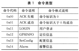
For example, when the transmitted data is positioning information, the frame data is in turn: a 16-byte R-uIM card number (usually 11 bytes), similar to a mobile phone number, when 16 bytes is insufficient, followed by 0x00; 1 word The length of the data content of the section is used to indicate the number of bytes of data content sent after the frame header of each frame; the 1-byte command identifier indicates the meaning of the transmitted data frame, and if it is the positioning information, it is sent 0x12; Followed by the data content. The data format of different information content is also specified in the communication protocol.
The system software works as follows: During the transportation process, the MCU uses the timer to periodically send positioning information to the monitoring platform server. The data format sent follows the communication protocol data format described previously. First, the MCU sends the positioning command "AT+GPSSRT" to the DTGS-800. After the CD-MA module completes the positioning, it returns the positioning information to the MCU. The MCU parses this information, extracts the valid information such as latitude and longitude and current time, and then converts the data; then sends the Internet access command “ATDT1123†to the module. After the data connection status is valid, it starts to send the positioning information to the monitoring server. When the travel switch is activated, first send the Internet command and alarm information, and then follow the above steps to communicate. The software flow is shown in Figure 5.
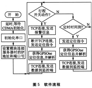
Note: The handshake mechanism, the response mechanism, is used when TCP connects and sends data. In order to make the flow of the system clearer, the handshake process is not shown in Figure 5. When the DTGS-800 module sends data to the monitoring terminal, the monitoring terminal needs to return the response signal according to the situation; if the module does not get a response within the specified time, the default is the connection timeout. In order to avoid a crash when the TCP connection process is not received, the system uses a timeout retransmission mechanism to ensure the reliability of the communication.
Conclusion
When the traditional GPS positioning technology is applied in logistics, in addition to using the GPS module, it is necessary to additionally use other auxiliary hardware such as the GSM module to realize the positioning alarm function. In the positioning terminal based on GPSOne technology, the DTGS-800 module combines various functions such as positioning, GSM and CDMA network services, with high integration and cost performance. The system test shows that the scheme achieves precise positioning in urban areas or indoors with dense buildings, which overcomes the shortcomings of GPS technology positioning blind spots. The system device is small in size and easy to install in the container of the item; the positioning data can be sent to the monitoring platform server of the logistics company through the network in time, which is convenient for real-time monitoring and management; and can also timely alarm when the item is stolen, facilitating logistics The company finds out the facts and investigates the responsibilities, which can prevent theft of employees inside the logistics company to a certain extent.
40Pin Ribbon Cable,Cable Ribbon,Flat Ribbon Cable,Custom Flat Ribbon Cable
Electronic Cables,Electrical Wiring Harness Co., Ltd. , http://www.nbwireharnesses.com