In today's increasingly tense energy and increasingly serious air pollution, the development of new fuel cell vehicles with independent intellectual property rights is an important leap and milestone of China's auto industry, and one of the main areas of national support. Compared with traditional fuel vehicles, fuel cell vehicles are environmentally friendly, energy efficient (hydrogen is fuel), stable and noise-free. At the heart of the fuel cell vehicle system is its power system, the fuel cell engine, which is equipped with a high-power lithium-ion battery that recovers downhill and braking energy. The entire vehicle system consists of several control units, each connected to each other via a car bus. The air conditioning control system is an auxiliary control unit for this new energy vehicle, but it is also an important part of the automotive system. This paper will present an intelligent node based on a general-purpose microcontroller (MCU) and a separate CAN controller and transceiver. The communication and control between the vehicle and the vehicle system is controlled by the digital signal processor DSP2407. The operation of the rotational speed air conditioning controller and the entire air conditioning system have been successfully operated in a fuel cell powered test vehicle.
1 CAN bus principle
This article refers to the address: http://
Controller Area Network CAN belongs to the field bus field. It is a serial communication network that effectively supports distributed control or real-time control. CAN is a multi-host local network originally introduced by Bosch in 1986, which was originally applied to the communication of modern automotive microcontrollers. It realizes the exchange of information between various electronic control devices. The International Standards Organization ISO has developed an international standard for regulating CAN bus. CAN has been recognized as one of the most promising fieldbuses, and it will play an increasingly important role in the development of today's automatic control field. The CAN protocol is based on the open system interconnection reference model OSI of the International Organization for Standardization (ISO). It mainly works on the physical layer, data link layer and application layer. Users can develop application layer communication protocols suitable for actual system needs. Signal transmission is generally done by twisted pair, coaxial cable or fiber. The CAN bus system has a long communication distance and a high communication rate. The maximum communication rate is up to 1 Mbit/s. When the signal transmission distance reaches 10 km, the data transmission rate of up to 5 kbit/s can still be provided. Due to this feature of the CAN bus, it is more conducive to the formation of large systems.
2 system hardware design
2.1 Air conditioning control system structure
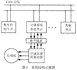
Since the entire automotive system is a complex control system, it can be divided into several modules or subsystems, each of which is responsible for performing certain functions. Each control unit is connected together via a CAN bus to form a local area network of a bus type structure. Although each node in CAN is in a peer-to-peer position, in order to better coordinate the various control units, the vehicle controller is used as the core control unit to control the operation of other electronic control units and the distribution of system power. The system CAN bus structure is shown in Figure 1. The air conditioning control system is used as a subsystem of the whole vehicle system on the one hand, and also as a node on the CAN bus. Its main function is to receive the control commands of the master control node and transmit the air conditioner related data to the master control node through the CAN bus. Control of the opening and closing of the car air conditioner, temperature setting, and temperature collection inside and outside the car. The communication between the air conditioning system and the vehicle controller on the CAN bus is very important, and the air conditioning control part involves the high voltage part. For the safety and reliability of the whole vehicle system, the CAN communication part of the air conditioning system and the compressor drive part are designed separately. The two are electrically isolated by a photocoupler to ensure safe and reliable communication between the air conditioning system and the vehicle.
2.2 Hardware Design
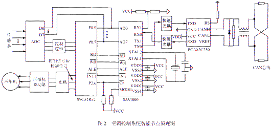
Since the amount of information processed by the intelligent node of the air conditioning control system is not very large, the communication with the main control node, that is, the vehicle controller is mainly completed, and secondly, the control of the air conditioner controller and the collection and display control of several temperature analog quantities are performed, so The selection of a microcontroller (MCU) with a versatile and flexible development and a separate CAN controller and CAN bus driver scheme is completed. The hardware design principle of the intelligent node is shown in Fig. 2. Among them, the intelligent controller uses P89C51Rx2 for the microcontroller, and the CAN interface consists of the independent controller SJA1000 and the CAN bus driver PCA82C250. SJA1000 is used as the off-chip expansion chip of the microcontroller MCU. The data transmission between the SJA1000 and the MCU is completed by the MCU data port P0, and the data receiving signal is interrupted to improve the real-time performance of data processing. The CAN controller SJA1000 is connected to the physical bus via the bus driver PCA82C250. The PCA82C250 device provides differential transmit capability to the bus and differential acceptance to the CAN controller. Differential drive helps to suppress transient disturbances in harsh electrical environments such as automobiles. In order to enhance the anti-jamming capability of the CAN bus node, the TX0 and RX0 of the SJA1000 are not directly connected to the TXD and RXD of the 82C250, but are connected to the 82C250 through a high-speed optocoupler. This is a good implementation between the transceiver and the controller. The electrical isolation protects the intelligent node core circuit from safe operation and achieves electrical isolation between the CAN nodes on the bus. In order to further enhance the anti-interference ability of the system, a bidirectional voltage regulator can be connected at the bus inlet to limit the short-term spike overvoltage that may occur on the line and increase the common mode suppression coil to eliminate the interference of the common mode signal. In addition, when the communication signal is transmitted on the line, the signal will be reflected when it is transmitted to the end of the wire, and the reflected signal will interfere with the transmission of the normal signal. In order to eliminate this effect, two 120Ω resistors can be connected to both ends of the CAN bus to match the bus impedance and eliminate the reflection. If these measures are ignored, the anti-interference and reliability of data communication will be greatly reduced, and even communication will not be possible.
In addition to the connection with the CAN controller, the MCU in the node also needs to complete the control and data acquisition of the air conditioning system. The collected data mainly includes the interior temperature, the air conditioning set temperature, the air conditioning coil temperature, the outside temperature, the sunshine intensity, and the pressure protection. The analog quantity is output to the air conditioner compression driver according to the collected data through the closed loop control mode, and the compressor driver will transmit the running status of the compressor to the MCU in real time. According to the status information, the MCU will handle it accordingly.
In Figure 2, the brushless DC compressor drive control part, its core control chip uses TI's motor control dedicated digital signal processor TMS320LF2407, due to its fast speed, can ensure the realization of complex system algorithms and the detection of the rotor . The position detection is realized by detecting the back electromotive force. In addition to completing the generation and position detection of the driving signal, the DSP also receives the command of the air conditioning intelligent node to start the compressor and feedback the compressor operating state.
3 system software design
The software design of the air-conditioning control system mainly includes the intelligent node part and the compressor control part. The intelligent node mainly completes the relevant initialization; temperature sampling; receives the control command of the main control node and sends relevant data, such as the upper limit of the power allowed by the air conditioner; And the set temperature value; the start signal sent to the air conditioner controller and the running frequency signal; the running state of the compressor and the fault handling are detected. The compressor controller part mainly completes the generation of the driving signal of the compressor, the processing of the position detection signal, and the start-stop signal and the operating frequency of the intelligent node of the air-conditioning. Due to space limitations, only the control node part of the program is discussed here. The main program flow chart of the control node is shown in Figure 3.

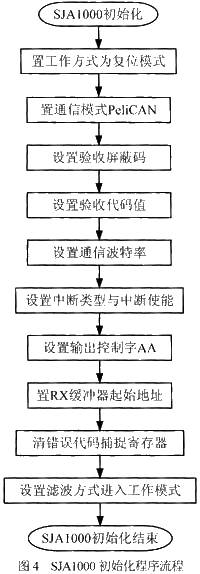
For intelligent node software design, it is mainly node initialization, message transmission and reception. For the node to work properly, the key is to initialize the node correctly. The initialization of the node mainly refers to the initialization of the microprocessor and the CAN controller SJA1000 after the system is powered on to determine the working frequency, baud rate and output characteristics. The initialization of P89C51Rx2 can be carried out according to the specific control object, mainly the use and setting of interrupts and timers, etc., which will not be described in detail here. This section mainly introduces the initialization of SJA1000. Since there is no microprocessor inside the SJA1000, its initialization is still to be programmed by P89C51Rx2. The SJA1000 initialization program flow is shown in Figure 4. The initialization of SJA1000 should be performed in reset mode, so in the SJA1000 initialization program, the working mode should first be set to reset mode, then the acceptance filtering mode, acceptance mask register (AMR) and acceptance code register (ACR), baud rate should be set. Parameters and interrupt enable registers (IER), etc. The synchronous jump width and the communication baud rate in the physical layer of the CAN protocol are determined by the contents of the timing registers BTR0 and BTR1. It should be noted here that for all nodes in a system, the contents of these two registers must be the same, otherwise communication will not be possible. After the initial setting is completed, the reset request position is “0â€, and the SJA1000 can enter the working state and perform normal communication tasks.
The designed CAN intelligent node has high reliability and superior performance and price ratio, especially the use of independent CAN controller to realize intelligent nodes with convenient implementation and good versatility. The whole air conditioning control system can well realize the communication with the main control node and the drive control of the brushless DC compressor, and the various operating parameters meet the design requirements. The automotive air conditioning control system designed in this paper has been actually operated on the fuel cell vehicle to meet the design requirements.
Cable and Wire,Electrical Wire ,Wire Cable ,Outdoor Electrical Wire
Cable Sleeve Co., Ltd. , http://www.nbshrinktubing.com