introduction
This article refers to the address: http://
The Musical Fountain is a combination of modern technology and art. It uses fountains to express the beauty of music and is pleasing to the eye. At present, many units have launched their own music fountains and achieved good results. But throughout these sound control products, some use the time domain changes of music to control the fountain, and some divide the music into several frequency bands to control the pattern of the fountain, and use three frequency bands of low frequency, medium frequency and high frequency to control. The disadvantage is that it does not display music well in the frequency domain, so it does not reflect the connotation of music well. In response to these problems, this design proposes a new method to control the change of the fountain, and the spectrum of the music is displayed in real time through the jetting height of the fountain water column.
Overall design
Firstly, the audio signal is preamplified by filtering, filtering, sampling and A/D conversion. After the Fourier transform is performed on the audio signal by the DSP, the spectrum of the audio signal can be obtained, that is, the intensity of the corresponding sound signal of each frequency can be controlled by the frequency conversion control system. The spectrogram is represented by the water column of the fountain, and the height of the water column reflects the amplitude of the audio signal in a linear ratio. Let the number of samples of the audio signal be n each time, and the overall structure of the system is shown in Figure (1).
Specific design
Chip and function module introduction
The TLV320AIC23 (referred to as AIC23) is a high performance multimedia digital speech codec with an internal ADC and DAC conversion module with a complete digital filter. There are 11 16-bit registers inside, and the control interface has SPI and I2C operation. The data transfer width can be 16 bits, 20 bits, 24 bits and 32 bits, and the sampling frequency range supports from 8 kHz to 96 kHz. The noise is 90-dBA when the ADC capture reaches 96kHz, which can save the audio signal with high fidelity. The noise is 100-dBA when the DAC conversion reaches 96kHz, enabling high quality digital playback of audio.
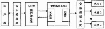
Figure 1 overall design block diagram
TMS320C6713 is a high-speed digital signal processor (DSP) produced by TI. It adopts advanced ultra-long instruction word (VLIW) structure and can execute 8 32b instructions per clock cycle. The maximum clock frequency can reach 300MHz and the instruction cycle is minimum. 3.3ns. The chip has a wealth of on-chip memory resources and a variety of on-chip peripherals, the external total memory address space of up to 512MB, data width of 32b, can support SBRAM, SDRAM, SRAM, FALSH and EPROM.
There are two multi-channel buffer serial ports (McBSP) in the TMS320C6713, which can easily use the two McBSPs to complete the control and communication of the AIC23.
Hardware connection
Connection of TMS320C6713 to TLV320AIC23
The two multi-channel buffer serial ports of TMS320C6713 are respectively configured as I2C mode and SPI mode McBSP0 as the data transmission port, McBSP1 as the control port, and the hardware connection diagram of AIC23 write control words TMS320C6713 and AIC23 are shown in Fig. 2.
The frequency conversion control system design variable frequency control system is composed of frequency conversion controller, frequency conversion distributor and frequency converter. For the control system of the control system below 8 channels, the control method shown in Figure 3 can be used.
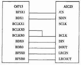
Figure 2 Hardware connection between TMS320C6713 and TLV320AIC23
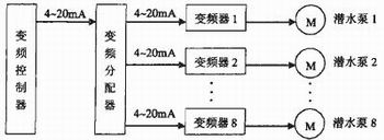
Figure 3 frequency conversion control system
The music signal processed by the DSP is automatically converted into a 4~20mA DC current signal required by the frequency converter. The output DC current signal is linear with the size of the input music signal, so that the spray height of the fountain varies with the size of the music signal.
For the multi-channel fountain control of more than 8 channels, the function of expanding the music fountain controller and the frequency converter demonstrator can be used to meet the requirements. DSP is used as the control center of the frequency conversion type music fountain control system. It will be expanded by 4 channels in the future, which are 4 channels, 8 channels, 12 channels, 16 channels, etc., and so on. Each channel controls a frequency converter to convert the music signal into a 4~20mA DC current signal that can be accepted by the inverter to drive the inverter, so that the spray height of the fountain changes with the size of the music signal.
Software Implementation
The presidential software design first initializes the McBSP0 port and the McBSP1 port, configures the AIC23, then starts the A/D conversion of the AIC23, samples the analog audio signal input by the microphone, and then performs Fourier transform on the sampled audio signal. The overall flow block diagram is shown in FIG. 4. Shown. The formula of Discrete Fourier Transform (DFT) is shown in Equation 1. In order to perform fast Fourier transform, a time extraction (DIT) basis 2 FFT algorithm is employed.
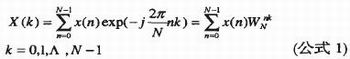
The FFT is performed on the N-point audio signal. It can be seen from Equation 1 that the frequency is also N points, and the frequency corresponding to the kth point in the frequency domain is fk, and the calculation formula is shown in Equation 2. Where fs is the sampling frequency of the audio signal, f'k is the normalized frequency, and the formula for calculating f'k is given in Equation 3. Therefore, from Equation 2 and Equation 3, the actual frequency value corresponding to each sample point on the spectrogram can be obtained.
![]()
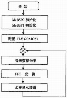
Figure 4 overall process block diagram
Audio data collection
1. Sampling frequency According to the sampling theorem, the frequency used should be at least twice the frequency of the sampling sound. Since the frequency that the human ear can feel is about 20 Hz to 20 kHz, the theoretical frequency is preferably 40 kHz. In fact, due to equipment, the frequency of adoption is generally 10% higher, that is, 44 kHz. Since the AIC23 supports 44.1 kHz, the sampling frequency in this design is 44.1 kHz.
2. Sample Size The sample size determines the difference between the lowest amplitude and the highest amplitude of the possible recorded sound, representing the quantized size of the sample. The intensity of the sound is proportional to the amplitude of the sound. Like the frequency, the human ear's ability to sense the sound intensity is not a linear relationship, but a logarithmic relationship, usually expressed in dB (decibel). The definition of dB is: 20log(A1/A2), and A1 and A2 are the two amplitudes of the sound.
When the size is 8 bits, then the maximum and minimum amplitude ratio of the sound is 256, then: 20log(256)=48dB. When the size is 16 bits, then the maximum and minimum amplitude ratio of the sound is 65536. : 20log (65536) = 96dB At this time, the maximum sound intensity is close to the limit of the human ear. In this design, the sample size is 16 bits.
3) Implementation of data acquisition
The programming steps are as follows:
a) Initialize the multi-channel buffered serial ports 0 and 1.
Initialization of the multi-channel buffered serial port is accomplished by configuring its registers. Serial port 0 is configured in the mode, and the serial port 0 registers are configured as follows: serial port configuration control register SPCR=0xC30003; interface control register PCR=0x03; receive control register RCR=0x0140; send control register XCR=0x0140. Serial port 1 is configured in SPI mode. The serial port 1 registers are configured as follows: serial port configuration control register SPCR=0xC51000; interface control register PCR=0xa0a; receive control register RCR=0; transmit control register XCR=0x10040.
b) Configure TLV320AIC23
There are 11 16-bit registers inside AIC23. Among the 16-bit control words, B[15-9] is the address of the register, and B[8-0] is the data to be written to the register. The values ​​written into these 11 registers for this design are as follows: left channel input control = 0x17; right channel input control = 0x17; left headphone channel control = 0x7f; right headphone channel control = 0x7f; analog audio channel control = 0x1c; Audio channel control = 0x1; start control = 0; digital audio format = 0x4f; sample rate control = 0x3f; digital interface activation = 0x01; initialization register = 0.
c) Start the conversion, perform A/D conversion, and store the converted data in the internal memory of the DSP, using 128 points each time.
Instance
Figure 5 shows the audio signal spectrum waveform of the simulation output in the DSP software environment CCS2.0, and Figure 6 shows the time domain waveform of the audio signal. The number of samples per time is 128, the sampling frequency is set to 44.1 kHz, and the sample size is 16 bits.
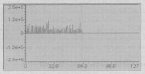
Figure 5 audio signal spectrum
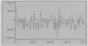
Figure 6 audio signal time domain waveform
Conclusion
This paper presents a new design scheme of musical fountains, and proposes a method to display the spectrum of music signals through the high and low variations of fountain water columns. The advantages of DSP and audio codec chips in audio signal processing are very Goodly used in the music fountain system. The software programming and hardware system design of the interface between TMS320C6713 and audio codecAIC23 are elaborated in detail. This solution achieved good results when running the simulator in the Code Composer Studio (CCS2.0) environment for joint debugging of software and hardware, which confirmed the success of the design and the availability of the solution. This program can not only be used as the front-end control system design of the music fountain, but also can be used as a model of the portable audio signal spectrum analyzer if an LCD display and some control circuits are added.
Generator Parts,Generator Monitor,Special Parts For Generator,Customized Generator Parts
Junction Box,Switch Co., Ltd. , http://www.nbsocket.com