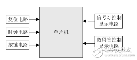
Figure 1: Block diagram of the traffic light control system hardware
The reset and clock circuits are standard modules, with a crystal frequency of 11.0592 MHz. The signal light control display circuit is illustrated in Figure 2. Twelve LEDs are controlled via the P1 port of the microcontroller, simulating real-world traffic signals. Specifically, P1.0–P1.2 control the red, yellow, and green lights in the north-south direction, while P1.3–P1.5 control the same colors in the east-west direction. All the signal lights are connected using a common anode configuration. When the corresponding ports output a low level, the respective LEDs illuminate, indicating the current traffic state.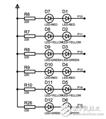
Figure 2: Signal light control display circuit diagram
A four-digit seven-segment digital tube is used to display the countdown for passage or stop. The digital tube control circuit is shown in Figure 3. The segment code for the digital tube is connected to the P0 port of the microcontroller, while the bit code is connected through the inverted phase of a transistor to the MCU’s A1–A4 ports. By sequentially controlling the bit code of each digit, the display updates dynamically. Since the digital tube uses a common cathode connection, both the segment and bit codes are active high.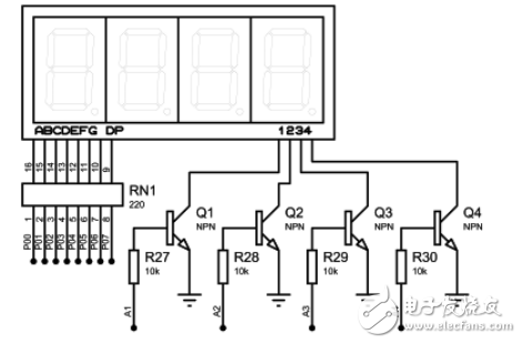
Figure 3: Digital tube control display circuit diagram
The function button circuit is shown in Figure 4. It includes three buttons labeled S1, S2, and S3, which are connected to the P2.0–P2.2 ports of the microcontroller. These buttons allow manual adjustment of the traffic light timings. Specifically, S1 is used for switching between adjusting the north-south and east-west directions, with one press for the north-south, two presses for the east-west, and three presses to exit the adjustment mode. S2 increases the timing by 1 second per press, while S3 decreases it by 1 second. The adjustment step can also be customized to 5 or 10 seconds, depending on user preference. Additionally, the system has upper and lower limits for the maximum and minimum allowable times.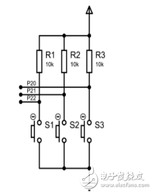
Figure 4: Function button circuit diagram
ZTTEK Batteries, For 5G backup base station .Customize the lithium ion battery packs according to the application and product requirements of the customers.
Lithium ion battery integration requires a special set of skill and expertise to optimize the performance and battery life.ZTTEK Batteries , using the most advanced technology delivers the best quality battery packs.
Our batteries are safe to use, better performance, higher shelf life and a very low maintenance cost.
48V200Ah Lithium Ion Battery,Lifepo4 Battery 48V 200Ah,Rechargeable Battery 48V 200Ah,48V 200Ah Lifepo4 Battery Pack
Jiangsu Zhitai New Energy Technology Co.,Ltd , https://www.zttall.com