Capacitive detection technology continues to be favored in traditional human-machine interface applications such as notebook trackpads, MP3 players, touch screen displays, and proximity detectors. In addition to using capacitive sensors instead of mechanical buttons, a little bit of imagination, combined with the basic principles of human-machine interface design, will enable many other applications to take advantage of this technology. Figure 1 shows some examples of application concepts that can be refined by using human contact detection.
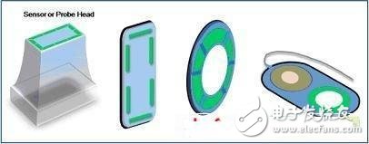
Figure 1. Device using a capacitive sensor electrode
For the device shown in Figure 1, it is often advantageous to know the quality of the contact between the device and the skin before starting the device or taking measurements. These devices include medical probes that need to be in close proximity to the skin, biopotential electrode sensors, or housings for securing catheter tubes. In order to determine the contact conditions, several green capacitive sensor electrodes in the figure can be directly embedded in the plastic housing of the device during the injection molding process. The host microcontroller reads some status registers on the capacitive sensor controller IC that indicate how close the capacitive sensor is to the skin. The basic detection algorithm running on the host microcontroller then processes the status register information to determine if the sensor electrodes are in proper contact with the skin.
In traditional capacitive detection human-machine interface applications, people generally begin to touch the sensor electrodes by finger touch. The example in Figure 1 uses a capacitive sensor in an unconventional manner, and the user places a device with a capacitive sensing electrode on the human body. Developing such an application is simple, but in order to build a stable and reliable system, some key guidelines should be followed.
Capacitance digital controller. To develop high-performance contact inspection applications, you first need to choose a suitable capacitor digital controller (CDC). For the application shown in Figure 1, the contact of the device surface with the skin is measured directly by subtle changes in energy that are distributed across the array of capacitive sensor electrodes that are created when the device comes into contact with the skin. The accuracy of this measurement depends on the sensitivity of the CDC analog front end and the number of sensor electrodes. Capacitive sensors fabricated using traditional PCB processes typically range in accuracy from 50 fF to 20 pF, making high-precision measurement techniques using 16-bit CDC ideal.
When choosing a CDC, first identify key features such as a high-resolution analog front end with a 16-bit ADC, programmable sensor sensitivity settings, programmable sensor offset control, on-chip environmental calibration, and adequate capacitive support for an ideal number of sensor electrodes. Input channels and integrated designs for sensor calibration without the need for external RC devices. These features support reliable and flexible applications for the best user experience. For example, programmable sensitivity allows interface designers to preset optimal sensor sensitivity for a specific application rather than a fixed solution that can result in poor sensitivity. Programmable offset control is another important feature for interface designers because the offset values ​​of the sensor boards for each production batch may vary slightly. Fast pre-characterization allows the host firmware settings to be changed before the new sensor board is put into mass production. For applications where ambient temperature or humidity is expected to change, on-chip environmental calibration enables a more reliable solution. Note that the electrode sensor is constructed using standard PCB copper traces; the properties of the substrate change with temperature and humidity, thus changing the baseline level of the sensor output. If the CDC supports on-chip calibration, this baseline drift can be dynamically compensated for in product use.
Small electrodes require high sensitivity. The goal of the measurement is to determine how close the device is to the skin; the better the quality of contact between the skin and the device, the more accurate the reading of the device. The accuracy of the measurement depends on the number of electrode sensors (the more electrodes, the higher the resolution) and the size of the electrode sensors distributed over the contact surface area of ​​the device. For the application shown in Figure 1, the surface area of ​​the device is typically small, requiring designers to use small sensor electrodes when developing applications.
In order to reliably measure small capacitance changes associated with small sensor electrodes (typically less than 50 pF), a high sensitivity analog front end controller is required. Keep in mind that the type and thickness of the plastic cover material will further affect the small signal emitted by the sensor through the plastic. The analog front-end measurement of the controller must have sufficient sensitivity to measure this small signal while measuring the signal and threshold voltage under all operating conditions (eg different supply voltages, temperature and humidity, and thickness and type of coverage material) Maintain a good signal margin between flat detection settings. A lower signal margin increases the risk of false detections and sensor instability. To minimize risk, when using a CDC with a 16-bit ADC, a margin of at least 1000 LSB should be maintained between the sensor baseline level (the sensor is not in contact with the skin) and the contact threshold level.
The AD7147 and AD7148 CapTouch programmable controllers are designed for single-electrode capacitive sensors with 16-bit resolution for femtofarad measurements and 16 programmable threshold detection levels over the full-scale range. Both controllers support 3 mm & TImes; 3 mm small sensor electrodes in 1 mm plastic overlay (dielectric constant 3.0) while still maintaining a full-scale signal margin of 1000 ADC LSB. The full-scale signal margin is the difference between sensor outputs without skin contact and skin contact.
Maintain reliability. Capacitive sensor electrodes are made of standard copper or flexible materials on the PCB. The properties of this material change with changes in temperature and humidity. This change shifts the baseline level (all sensor thresholds are referenced to the baseline level). A large baseline offset increases the risk of the contact threshold level being too low or too high (too low or too high depending on the direction of the baseline offset) which can cause false contact errors or make the threshold level not too sensitive Not sensitive enough to cause instability in contact. To maintain the sensor's original signal contact threshold detection level margin (sensitivity), the CDC needs to automatically track the magnitude of the baseline offset error and re-adjust the threshold settings accordingly. The example in Figure 2 shows how the threshold levels of the AD7147 and AD7148 automatically track and adjust for baseline offset changes due to changes in environmental conditions.
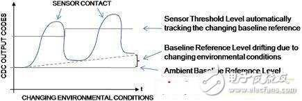
Figure 2. AD7147/AD7148 On-Chip Environmental Calibration
Eliminate measurement errors. The modification behavior of incorporating a capacitive sensor electrode array within the device can create space constraints, forcing the designer to place the CDC away from the capacitive sensor. This increases the length of the parallel sensor traces and makes the wiring dense, which is not conducive to capacitive sensing applications, because traces at different DC potentials will form the stray coupling path shown in Figure 3A. The ground plane of the PCB does not prevent this because stray capacitance is still formed because the trace and ground plane are at different DC potentials (Figure 3B).
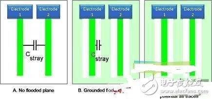
Figure 3. The path of the stray capacitance, showing the following results of the walking line: the parallel line without the copper layer (A), the parallel line on the grounded copper layer (B), and the same DC as the trace And the walking line on the copper layer (C)
To eliminate stray capacitance errors, one method is to surround adjacent traces with a layer driven by a DC level (the DC level is the same as the DC level of the capacitive sensor electrodes and traces). The AD7147 and AD7148 devices eliminate stray capacitance by providing a dedicated ACSHIELD output with this capability, as shown in Figure 3C.
Consumer health care equipment such as spa skin care products are entering the general family from professional institutions, and users are no longer the technicians who are specially trained and familiar with the products and their applications. Therefore, many of these products require a smarter user interface to enable untrained users to master the correct product usage. Capability testing provides a new choice for user interface designers to explore innovative ways to meet new user interface needs. Capacitive digital technology provides contact information between the capacitive sensor electrodes and the skin to maintain optimal product performance and safety.
ZhenHuan's non-dimmable metal material case led drivers provides the input voltage 120 volts 60Hz and 3 years warranty. The series Led Power Supplies is Iron materials housing junction box Power Supply with IP20 rated and are suitable for indoor installations, offers both ETL/cETL Class 2 FCC RoHS Listed style enclosures, high PFC more than 0.95.

120VAC Input Non Dimmable Led Driver
Electronic Led Driver,Driver Input 120V,Led Lighting Suppliers,Led Strip Light Drivers,Led Transformer Junction Box,Led Drivers for Sale
Shenzhenshi Zhenhuan Electronic Co Ltd , https://www.szzhpower.com