0 Preface
In the field measurement, it is often encountered that the measuring points are distributed linearly, for example, transmission lines, oil pipelines, rivers, urban pipe networks, etc. These monitoring data have the following characteristics:
(1) The separation distances are different. For example: the flow pressure of the oil pipeline, the monitoring point can be 1 km; the urban street lamp damage is monitored by 25 m.
(2) The transmission rate is not high. For example: monitoring of street lamp damage, coal mine tunnel slope monitoring, can be a few minutes, water quality along the river, temperature information can even be hourly.
(3) The physical order of the measuring points can be used as the logical order of the monitoring points. As long as the data of each point is sequentially detected, a certain number of data is not required to be transmitted separately.
(4) There are a large number of measuring points, for example, there are 400 street light monitoring points with a length of 10 km.
For the linear distributed measuring points often encountered in the field, if the bus type networking structure is adopted, the wiring form can be simplified very well, and all the measuring points can be connected to the bus. In fact, there are many such buses to choose from, such as CAN bus, 485 bus, IEEE1394 bus, Profi-bus bus, HART bus, and even devices with self-contained bus, such as digital temperature sensor DS18B20. But these solutions are It is not tailored to the above data characteristics, some pursue high reliability, some pursue network speed, and there are also problems such as high cost, complicated protocol, and need to address each site by measurement [3]. Therefore, this paper proposes a three-wire networking scheme based on single-chip microcomputer for linear measuring points. It has the characteristics of self-contained power supply, simple protocol, flexible and variable, which can greatly simplify circuit design and system design.
1 System structure and principle
1.1 Hardware composition
1.1.1 Overall composition of the system
The composition diagram of the three-wire measurement system is shown in Figure 1. It consists of a main unit and several units. The three lines are defined as power, signal, and ground. The main unit can control the power supply of the unit, which is completed by switch J1. It can be the hard contact of the relay or the soft contact of the VDMOS tube. When the host needs to collect data, first close J1, power on all the units, and then control each unit to upload data sequentially through the signal line R/T. Among them, 1, 2, ..., N represents N measurement units.
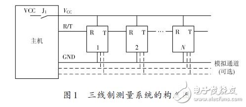
If an analog signal needs to be transmitted, an additional analog signal bus is added. The unit structure is shown in Figure 2.
1.1.2 Unit structure
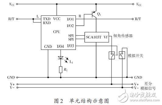
The internal composition of the unit varies according to the measurement parameters. Here is an example of the inclination measurement. Using the inclination sensor, the schematic diagram is shown in Figure 2. The power-on measurement is performed automatically. After the completion, the input terminal R waits for the start pulse, and then enters the unit data transmission. During this period, the unit is directly connected to the host. When the data transmission of the unit is completed, the end pulse of the input terminal is waited. Then the unit sends a start pulse to the lower unit, and then the unit enters a transparent transmission (or microphone) mode, which is equivalent to straight-through, the host can communicate with the next unit, and so on.
In the unit structure intent, two analog signal lines have been added because the tilt sensor has both a digital output (through the SPI interface) and an analog output (via the Vf terminal). If you want to directly capture the analog quantity of the unit, add the analog switch and the analog signal bus. When the unit is in the working state, close the analog switch and send the analog quantity to the bus.
1.2 Working principle
When the host initiates a data acquisition, first close the switch J1, the bus VCC is powered, all the units are powered on at the same time, and the single-chip microcomputer in the unit starts to work. The unit's work is divided into three modes: standby, work, and transparent transmission. After power-on, all units enter standby mode. The host first sends a start pulse to the nearest 1# unit. The 1# unit changes from “standby†to “working†mode. It activates the sensor and lights the indicator L1 to indicate this. The unit is active. At this time, the host can directly communicate with the 1# unit, command the 1# unit to measure and read the data. After the completion, the host sends the end pulse, and the command 1# unit ends the active state. The 1# unit enters the transparent transmission mode after transmitting the start pulse to the 2# unit. Then, the start pulse issued by 1# is received, and the 2# unit becomes the active unit, and the indicator light L1 is turned on to enter the operation mode. Due to the transparent transmission of the 1# unit, the host can communicate directly with the 2# unit until the 2# unit receives the end command, it starts the next unit, and then becomes transparent, so that each unit becomes one by one. In the active unit, the host always communicates directly with the active unit through the unit that has become the transparent transmission mode to acquire data until all units complete the data collection.
Therefore, in the entire three-wire network, only one is the active unit, and the front of the active unit is the unit that completes the data collection and becomes the transparent transmission mode; behind the active unit, it is the standby unit waiting to be started. The host can directly contact the active unit, using flexible protocols and rates, which is a big advantage of the proposed three-wire linear networking.
When the host communicates with the active unit, the serial communication mode of the single-chip microcomputer can be directly used. When the amount of data is small, it is agreed to use a lower baud rate to obtain a longer transmission distance. The pulse command used to start and stop the unit can be in two forms:
(1) directly use serial communication to change the working mode of the unit, as long as the serial data command word sent by the host to the unit is agreed, for example, 0X55 is the start command, 0XAA is the stop command; (2) the pulse width control is used. As long as there is a significant difference between the command pulse and the communication baud rate communication pulse, there is no confusion. For example, the baud rate uses 1 200, and the start and stop pulses use a low level of 30 ms.
1.3 Characteristics Analysis
Summarizing the above explanation, the three-wire linear network proposed in this paper has the following characteristics:
(1) Self-contained power supply: There is one power line in the three lines, all units can directly power; (2) Low power consumption: only one unit is active during operation, and the unit in standby and transparent transmission mode can be turned off. The power supply of the sensor under its jurisdiction only charges the MCU. If the MSP433 ultra-low-power MCU is used, the power consumption of 100 units will not exceed 1 mA.
(3) Flexible protocol: The host communicates directly with the active unit through the transparent transmission unit, allowing the system builder to use its own agreed communication protocol; (4) The transmission distance is far: the host communicates with each unit through the relay, as long as each The units can be effectively transferred, and the entire system composed of multiple units can work normally.
(5) Convenient expansion: When mode transfer is required, as long as a bus is added, each unit adds an analog switch, and the active unit closes the analog switch. The analog quantity of the unit can be uploaded to the bus and sent to the host.
(6) No unit number is required: The host is in order to establish contact with each unit. All units are identical, and there is no address number link, which is suitable for mass production.
High Frequency AC Power Supply
Adapter Power Regulated,Ac To Dc Regulated Power Supply,High Voltage Regulated Power Supply,High Voltage High Frequency Power Supply
Yangzhou IdealTek Electronics Co., Ltd. , https://www.idealtekpower.com