1 Introduction
In the field of electronic consumer, the use of infrared products is more common. It is mostly used for simple close-range control, such as home appliances, toys, and various meter reading systems. This article takes Freescale 8-bit high-performance, low-power single-chip MC9S08GT60 as a carrier, detailed introduction of infrared communication hardware and software design process and the use of communication protocols.
The HCS08 series of MCUs are the latest 8-bit microcontrollers from Freescale Semiconductor. They have multiple low-power modes, higher operating frequencies, integrated on-chip debuggers, and rich resources. Therefore, the MC9S08GT60 of this series is used as a carrier. A simple and practical infrared communication development system is discussed.
The infrared communication process is mainly composed of infrared transmission and infrared reception. First, the digital signal is sent to the infrared transmission circuit, which is converted into an infrared light signal by the modulation of the circuit and transmitted in the air. Then the infrared reception circuit receives the infrared light signal and passes through The demodulation of this circuit restores this infrared light signal into a signal that can be processed by the single-chip microcomputer, and the original data code is obtained by the internal processing of the single-chip microcomputer.
2 Infrared communication protocol
The purpose of the agreement is to give the sending and receiving parties an agreement so that they can synchronize and send and receive data correctly. This design uses a synchronous protocol. When the infrared receiver does not receive the signal, the timing operation is not generated, otherwise, the start bit '0' is received first, and an interrupt is triggered, the timer is started to receive data, and then it is judged whether it is the start bit, and if it is, then continue to receive Data, otherwise reset the timer and re-detect the start bit. When receiving the second stop bit, an interrupt will be triggered to detect whether the stop bit received for the first time is correct. If it is not correct, reset the timer and re-receive , Otherwise the data segment has been received correctly.
3 Principle analysis of infrared communication
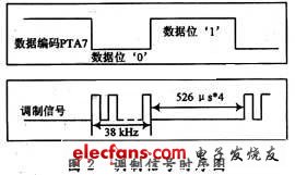
Infrared communication transmits a carrier signal in the air. When a carrier wave passes through, the receiving end outputs a digital signal '0', otherwise, it outputs a digital signal '1'. Therefore, the function instruction code sent in the transmitting circuit generally adopts a multi-bit binary serial code. In this paper, infrared communication data uses pulse coding, that is, each data signal is represented by a pulse with a pulse width of 526 μs, two such pulse periods represent '1', and one such pulse period represents '0'. Such pulse signals are modulated on a carrier with a frequency of 38 kHz and then sent out. The modulated signal transmitted in the air is a carrier signal with a certain time interval, and its duty cycle is determined by data encoding. At the infrared receiving end, the process of data processing is just the opposite. After receiving the infrared light signal, it undergoes a series of processing such as shaping, amplification, filtering, and modulation, and then outputs a series of data signals that can be processed by the single-chip microcomputer at its output.
4 Infrared communication hardware design principles
4.1 Hardware design of sending circuit
There are two TPM modules inside the HCS08GT60 MCU, each module has two channels, and you can use any PWM function of the channel to output a 38 kHz carrier signal. In this article, the TPM1 channel 1 center pulse width output is used according to the experimental conditions. The function generates a 38 kHz infrared carrier signal. The PTA7 port is used as an ordinary input and output port to generate a square wave signal with a certain pulse width, which is input as a data encoding signal. The hardware schematic diagram is shown in Figure 1.
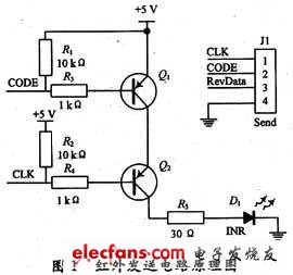
In the schematic diagram, the electrical node CODE is connected to the PTA7 port to generate the data code; the electrical node CLK is connected to the TPM1 channel 1 to generate a 38 kHz infrared carrier signal. The resistor connected in series with the base of the transistor and R5 play the role of current limiting protection. The transistor itself has the function of signal amplification. The other two transistors are cascaded and the code modulation is transmitted on the 38 kHz carrier through the infrared transmitter. When the code is '1', Q1 and Q2 are cut off, no current passes through the infrared transmitter, and a low-level signal is transmitted. When the code is '0', Q1 and Q2 are turned on, and the carrier signal is amplified by Q2 during transmission The transmitter reflects the 38 kHz carrier signal. Therefore, different data codes are input to the PTA7 port. Through this sending circuit, a 38 kHz carrier signal with a certain interval will appear on the transmitter, and the carrier signal will be converted into an optical signal by the transmitter and transmitted. The timing diagram of the carrier pulse modulation signal is shown in Figure 2.
4.2 Hardware design of receiving circuit
The HS0038A receiver is used in the infrared receiving circuit. The internal logic block diagram of HS0038A is shown in Figure 3.

It can be seen that the receiver realizes infrared receiving, amplification, filtering and demodulation functions. When the infrared carrier light signal is received, the infrared receiver outputs a low level, otherwise the infrared receiver outputs a high level, so that The intermittent infrared light signal is modulated into a continuous square wave signal, which can be converted into the original data by the internal processing of the single chip microcomputer.
The hardware schematic diagram is shown in Figure 4.

Because HS0038A has built-in filtering and uses epoxy plastic packaging, it can be used as an infrared filter, so no additional filter is needed in the circuit, and HS0038A has strong anti-interference ability.
The infrared receiver output pin RevData is connected to TPM2 channel 0, using the input capture function of TPM. The input capture occurs at the rising edge. The value of the channel register TPM2C0V is compared when two captures occur, and the width of one cycle pulse can be obtained according to The timing diagram of the transmitted data, you can know what the data corresponding to different pulse width is, and thus you can restore the original data.
Mini Cool Mist Usb Air Humidifier
Mini Humidifier is a vase shaped humidifier with lightweight and compact design. With ultrasonic technology, it envelops your surroundings effectively by producing cool mist to add moisture and relieve stress. Suitable for your car, office, bedroom, study room, dining room, children's room and more.
Features
- Mini Cool Mist Humidifier: Designed with high-frequency atomizer plate. It adopts ultrasonic technology to oscillate and decompose water into fine nano-class cool mist molecules, which can quickly penetrate the underlying skin and relieve dry skin.
- User-friendly Design: Lightweight and compact, this Mini Air Humidifier can hold up to 80ml of water and produce up to 25ml of moisture per hour. Both the main engine and water cup are detachable, easy to clean and use.
- Whisper-quiet: Ultra-stable atomizer plate provides gentle and stable mist, creating a quiet and relaxing environment (less than 35dB). Low consumption and low noise make it perfect for sleeping or reading time. Work quietly without producing any bothering noises.
- Safe and Reliable: With the built-in water level sensor, Mini Usb Humidifier will automatically power off when the water level is lower than the safe water level. Compatible with any USB power source (AC power adapters, car chargers, laptops/computers, or power banks), universal and convenient. Safe with a 5V low voltage input.
Mini Humidifier
Mini Humidifier,Mini Usb Humidifier,Mini Air Humidifier,Mini Cool Mist Humidifier
Shenzhen Dituo Electronic Co.,Ltd. , https://www.sz-dituo.com