1 Basic theory of word clock synchronization
In order to meet the challenges brought by the era of high-definition and meet the production conditions of surround sound, all major domestic TV stations have adopted a fully digital audio system in the high-definition TV studios and OB vehicles that have been put into use. Therefore, it is necessary to clarify some basic theories about word clock synchronization.
1.1 Word clock synchronization
Starting from the analog era, the most common synchronization method is the time code (TIme Code, or TC code) synchronization method, that is, to determine a unified time code in an audio system, all devices are based on this time code, from the same Start playback or recording at the time point. Throughout the process, the time code scale displayed on all devices is exactly the same. This synchronization method is still used in digital audio systems.
Word clock synchronization can only be used in digital audio systems. The word clock (Word Clock) is regarded as a kind of pulse signal, used to coordinate digital audio signals of different sampling frequencies to communicate in the same system.
The word clock signal has an accurate and stable sampling frequency, which can ensure that in each link of the digital audio system, the sending end and the receiving end of the signal work with the same sampling frequency, and the bits in the sending and receiving signals start simultaneously. Under the effect of the word clock signal, each device in the system achieves both frequency synchronization and phase synchronization, and can continue to work normally under stable conditions.
The word clock synchronization method plays a great role in stabilizing the transmission quality of digital signals in the system. However, when there is a problem with the word clock synchronization status of the system, which results in a serious degradation of the signal quality (for example, the transmission of the word clock signal causes an extreme noise in the system), sometimes it is often ignored and the direction of the word clock is often ignored. To solve the problem. This is because the effect of this synchronization method in actual operation is not as intuitive as the time code synchronization method.
1.2 Set the word clock synchronization status of the system
To achieve the word clock synchronization state of the digital audio system, a (and only one) word clock signal generation source must be set in the system. In fact, digital audio equipment such as digital mixers and digital audio workstations can generate word clock signals themselves, but only one word clock signal source can be set in each digital audio system, because the word clock in each device The signal determines the sampling frequency in this device. If different word clock signals appear in a system, it means that the sampling frequency in this system is not uniform, and it will not reach the synchronous working state, which will cause noise and other problems. Therefore, when using a digital audio system, the first step is to select one of the devices and set it as the source of the word clock signal in this system, that is, the synchronous host. The word clock signal generated in the synchronous host is called the master clock of this audio system.
In actual work, usually choose a dedicated word clock signal generator or digital audio mixer, digital audio workstation as the synchronization host (MaSTer) in the system. Set the synchronization mode of the device selected as the master to "Internal". At this time, the word clock signal generated inside the host will be transmitted as the master clock of the entire system to each slave device (Slave) that needs to be synchronized. The synchronization mode of each slave device in the system must be set to "external", and to ensure that each slave device can receive the word clock signal from the host steadily. When the whole system reaches the synchronous state, all the slaves in the system will work according to the sampling frequency determined by the master clock of the master.
1.3 The transmission method of the word clock signal in the system
The word clock signal can be transmitted in two ways.
(1) Use the coaxial cable of the BNC connector to directly transmit the word clock signal in the synchronous master to the slave
In this way, the word clock signal transmission structure in the digital audio system can adopt a star structure or a daisy chain structure.
In the star structure shown in Figure 1, the word clock signal of the master is output by the word clock signal dedicated output interface WC Out of the host, and then is transmitted to the word clock signal dedicated input interface WC In of each slave through a signal distribution amplifier . At this time, each slave in the system independently receives the word clock signal from the master and does not interfere with each other.
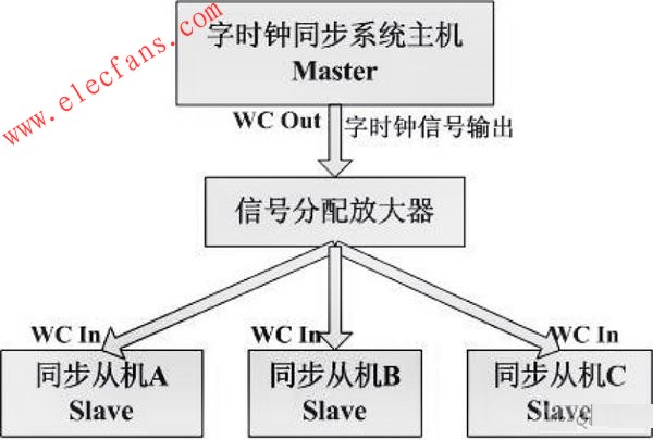
Figure 1 star structure.
In the daisy chain structure shown in Figure 2, the word clock signal of the master is output from the dedicated output interface WC Out of the word clock signal of the host, and then directly input to the dedicated input interface WCIn of the word clock signal of the slave A, and then continuously Transfer to the next stage until the word clock signal is input to the WC In of the last slave in the system.
The daisy chain structure has certain disadvantages compared with the star structure, because in this signal transmission structure, the slaves are mutually dependent. Once one of the slaves fails, the word clock signal cannot be transmitted to Among all the slaves below this slave. Moreover, in normal operation, all devices connected in a daisy chain structure in the system must be turned on regardless of whether they are used, and set to the normal word clock synchronization state, otherwise it will cause the subordinate devices to not get the input of the word clock signal.

Figure 2 daisy chain structure.
(2) Read the word clock signal from the digital audio signal transmitted in the system
Not all digital audio signals in all formats are suitable as read sources for word clock signals. When selecting the read source for word clock signals, it is necessary to refer to the interconnection standard of the digital interface of the specific device. In the current digital audio system, stable clock information can be read from common AES / EBU, MADI and other format signals.
The AES / EBU format is also known as AES3. It establishes a standard for transmitting a dual-channel audio signal that is periodically sampled and uniformly quantized using a single twisted pair. It can transmit data to a distance of 100 m or more without equalization. local. AES / EBU format audio signals use balanced transmission in most cases, that is, use XLR connectors at the input / output, but unbalanced transmission can also be used, that is, use BNC connectors at the input / output. When a device transmits signals according to the AES / EBU format, the clock information in this device is encoded according to the two-phase marking method and embedded in the data stream of the AES / EBU signal. At this time, the device receiving this AES / EBU signal can read the word clock signal from the device that outputs the signal in the signal, so as to achieve synchronization with the device that outputs the signal.
Multi-channel digital audio interface format (MulTIchannel AudioDigital Interface), also known as MADI, also known as AES10, can transmit 56 channels of digital audio signals through a 75 Ω coaxial cable with BNC connector within a distance of 50 m. In terms of word clock signal transmission, MADI is different from AES / EBU. The clock information of the device that outputs the MADI signal is not included in the MADI signal and is transmitted together with other audio information. This is called asynchronous operation. In order to enable the device that receives the MADI signal to synchronize with the device that outputs the signal, the MADI standard stipulates that the MADI signal transmits a 10-bit synchronization flag from the device that outputs the signal at least once per frame during transmission, so that the device that receives the signal can Extract the time base information from the transmitted data, and convert it into a word clock signal that can synchronize itself with the device that outputs the signal.
In this way, the transmission structure of the word clock signal in the system is the same as the transmission structure of the digital audio signal in the system.
The digital audio system in actual work is often more complicated. It may happen that some devices in the system receive the word clock signal directly from the coaxial cable connected to the dedicated input interface for the word clock signal, while another part of the device transmits the digital audio signal from the system. The case of reading the word clock signal. It may also happen that the same coaxial cable using the BNC connector directly transmits the word clock signal, partly connected in a star structure, and partly connected in a daisy chain structure. In any case, as long as the word clock signal used by each device is derived from the main clock of the system, the system can maintain a synchronized state.
2 Application of word clock synchronization
The following describes how to set the interconnected digital audio devices to the word clock synchronization state in a specific digital audio system.
The system is a large-scale digital audio system that can be used to make music recordings, and can also be used for post-production of film and television programs. It supports 5.1-channel surround sound production. Its core is the large digital mixer SOUNDTRACS DS-00 and Pyramix digital audio. Workstation, a brief signal flow is shown in Figure 3.
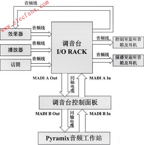
Figure 3 The signal flow of the audio system in a music recording studio.
As shown in Figure 3, the direction of the arrow represents the transmission direction of the audio signal. The control panel of the DS-00 mixer is the center of the entire signal flow and is responsible for receiving and distributing signals from various devices in the system. There are two sets of MADI format signal interfaces on the control panel of the mixer, namely MADI A and MADI B. The input and output of all devices in the system (except the Pyramix audio workstation) are connected to the corresponding signal format (analog or AES / EBU) interface on the I / O RACK of the mixer through the audio cable (XLR connector) . The signal is transmitted in MADI format between the I / O RACK and the control panel of the mixer, and is connected to the MADI LINKS A IN / OUT interface on the back of the control panel through two coaxial cables of the BNC connector. The MADI format is also used to transmit signals between the Pyramix audio workstation and the control panel, and it is connected to the MADILINKS B IN / OUT interface on the back of the control panel through two coaxial cables with BNC connectors.
2.1 Use a dedicated word clock signal generator as the system synchronization host
In this digital audio system, a high-precision digital clock generator LUCID SSG192 is installed, as shown in Figure 4. It is suitable for most digital audio systems, has an intuitive and convenient control panel, only occupies a single rack space, and can stably output a word clock signal with a sampling frequency between 32 and 192 kHz for a long time.
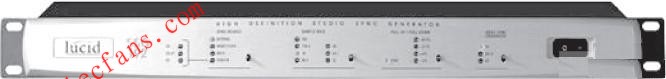
Figure 4 Dedicated word clock signal generator LUCID SSG192.
As the synchronous host of this digital audio system, LUCID SSG192 generates the required word clock signal, and then transmits the signal to the signal distribution amplifier LUCID CLK × 6 through the coaxial cable. LUCIDCLK × 6 has a total of 6 interfaces that can output the word clock signal on the fuselage. The word clock signal can be distributed to the DS-00 mixer, Pyramix audio workstation, TC SYSTEM-6000 effect device, DAT machine and other digital devices.
In actual operation, you need to select the required sampling frequency on the control panel of LUCID SSG192, and then set it in the menu of each digital audio device that needs to receive the word clock signal, and select their synchronization method as the external word clock. Signal synchronization. In this way, after the word clock signal is directly input into the dedicated interface of the word clock signal of each device through the coaxial cable, each device will adjust its own sampling frequency according to the sampling frequency of the word clock signal, and finally achieve synchronization with LUCID SSG192. The word clock signal transmission structure is a standard star structure, see Figure 5.
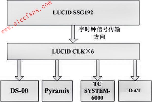
Figure 5 uses a dedicated word clock signal generator as the system synchronization host.
2.2 Using Pyramix digital audio workstation as the system synchronization host
In general, when there is a dedicated word clock signal generator in the system, it is recommended to use a dedicated word clock signal generator as the synchronous host of the system, because the word clock signal generated by the dedicated word clock signal generator is more stable . When there is no dedicated word clock signal generator in the system or the word clock signal generator cannot be used, a digital mixer or digital audio workstation is usually used as the synchronization host of the system. The following introduces the method of using Pyramix audio workstation as the synchronization host of the system.
First, you need to select its synchronization method to be synchronized with the internal clock (Master) in the menu of the Pyramix audio workstation, and then select the source of the word clock signal for each device according to the signal format transmitted in the system. For example, the MADI format is used to transmit signals between the DS-00 mixer and the Pyramix audio workstation. Therefore, you can select the MADI option in the DS-00 synchronization setting menu, and select a MADI channel that outputs signals from Pyramix to the DS-00. The signal transmitted in this channel is used as the read source of the word clock signal. At this time, DS-00 reads the synchronization flag sent according to the MADI format from the coaxial cable that transmits the signal from Pyramix to DS-00, and converts it into a word clock signal to adjust its sampling frequency. The TC SYSTEM-6000 effector is not directly connected to the Pyramix audio workstation. Its input / output interface is connected to the mixer's I / O RACK through an audio cable, and AES / is used with the mixer's I / ORACK. The EBU format transmits signals, so you need to select the AES / EBU option in the SYNC setting menu of the SYSTEM-6000 effector, and select an AES / EBU channel of the I / O RACK of the self-tuning console to input the signal to the SYSTEM-6000. The signal transmitted in this channel is used as the read source of the word clock signal. At this time, since the DS-00 mixer and the Pyramix audio workstation are synchronized, the DS-00 mixer and the Pyramix audio workstation use the same sampling frequency in their work. In this case, the SYSTEM-6000 uses the DS-00 00 The clock information in the audio signal of the mixer adjusts its own sampling frequency, so that the sampling frequency of SYSTEM-6000 and Pyramix audio workstation has actually reached an agreement. At this time, the transmission direction of the word clock signal in the system is consistent with the transmission direction of the audio signal, see Figure 6.

Figure 6 uses Pyramix digital audio workstation as the system synchronization host.
3 Conclusion
The word clock synchronization method in the digital audio system is a relatively complicated problem. Today, with the rapid development of radio and television technology, the use of digital audio equipment is becoming more common, and digital audio systems are becoming more and more complex, the author believes that it is necessary to continue to conduct more in-depth research on this issue. In addition to the examples described in the article, there are many ways to set the digital audio system to the word clock synchronization state in daily work. As long as you master the basic principles of word clock signal synchronization, you can achieve synchronization of digital audio systems in any case.
Solar street lights have been available for quite a time now, having originally been designed for use in less developed or isolated areas, or perhaps places where the electricity supply has been disrupted by man-made or natural disasters.
The technology guiding the use of solar energy has progressed significantly to enable projects to be feasible throughout the world. The situation now is that street lights powered by solar energy can be simply and rapidly installed, giving the potential of many years of trustworthy use, with a minimum of maintenance required.
Led Solar Street Light,Solar Road Light,Solar Post Lights,Solar Path Lights
Yangzhou Beyond Solar Energy Co.,Ltd. , https://www.ckbsolar.com