Editor's note-This is a good article that has been written for a long time. It was published on the short song line website at the time shortly after the launch of the Hivi M-200 speaker. The author is our old friend ndly01. It has been nearly three years since the M-200 came out, and the multimedia speaker market has changed a lot, but the M-200 still has a large user base as the main 2.0 product of Hivi. In fact, at the beginning of its advent, many professional commentators believed that-although the M-200 is a pioneering work of high-level 2.0-channel active speakers, and the sound performance has a certain quality, it is never perfect, and it has been modified and modified. Room. So this "Huiwei M-200 Multimedia Speaker Circuit Motor Talk" is a reference value for friends who have the intention to use their DIY capabilities to transform M-200 speakers. Due to negligence in work, after the opening of the new version of the website, this article was omitted from our library, and here we made new layouts and minor modifications, and republished it.

I often see many netizens commenting on the Hi-Vi M-200 multimedia speakers in major audio forums and seek ways to improve them. I have also seen many experts' insights and feelings after practice. Here, the information I have learned from myself is combined with the opinions and methods of the Internet users of the forum to talk about the M-200 circuit part (the M-200 is referred to as M-200). First of all, I was fortunate to see a post about the printed circuit board (PCB) of a M-200 in a post. After a night of hard work, I drew the circuit diagram of the M-200 (tragic! I actually would not Use protel and other circuit design software, only one stroke to draw with windows drawing!), All circuits see below:
figure 1
figure 2
image 3
The component table is shown in the table below. Because the resistance and capacitance components of the left and right channels have the same value, the circuit diagram uses the right channel as a model to explain. Looking at this table, you can see the corresponding component identification.
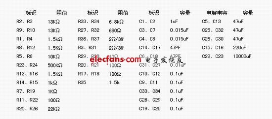
M-200 circuit component table

LM1875 main performance parameters
Before talking about the circuit briefly here, the entire circuit of the M-200 consists of the power supply section in Figure 3, the pre-tone control section in Figure 1, and the post-amplification section in Figure 2.
It can be seen from the figure that the M-200 uses the integrated power amplifier device LM1875 of the National Semiconductor Corporation (NSC) to complete the audio amplification. The LM1875 is also regarded as a monolithic integrated power amplifier device with excellent performance, which has low distortion and work. Stable and reliable, less peripheral circuit components, large current load capacity, etc., its main electrical parameters are shown in Table 2. I remember that in the past few years, this integrated block was very popular among the earthworm enthusiasts. It is probably due to the leap in people ’s fever concept, and the LM1875 has gradually been diluted. However, in view of the domestic multimedia speakers, it is rare to use the LM1875. Poor, most of them use things like TDA2030. The output power of the LM1875 can reach 30W at ± 30V power supply and 8Ω load. However, because the DC voltage provided by the M-200 transformer to the LM1875 is only 23V, the output power of the LM1875 here can only reach about 20W.
In Figure 2, LM1875 is connected as an AC negative feedback amplifier circuit, P1 is a volume potentiometer, C32 is a coupling capacitor, R26 is a bias resistor, and also determines the input impedance of the circuit. R33, R27, and C26 form a feedback circuit. Closed-loop gain K = 1 + R33 / R21 = 11 times, R29, C31 form a phase shift compensation network to prevent the generation of high-frequency oscillations.
The pre-stage of M-200 is the input buffer and negative feedback tone control circuit composed of op amp JRC4558, see Figure 1. The circuit in the left frame is a buffer stage with amplification factor K = R13 / (R19 + R22) = 1.3 times, C13 is the input capacitor, the capacity is 47uF, and the input impedance of the circuit = R22 + R19 = 1.1k. After the buffer stage, the signal is directly coupled to the typical negative feedback tone control circuit in the right frame. The advantages of the negative feedback tone control circuit are:
â‘ Due to the effect of negative feedback, the frequency distortion is reduced:
â‘¡ Due to the role of the amplifier, the mid-frequency attenuation caused by the attenuated tone loss controller can be compensated.
Figure 3 shows the power supply circuit. After 220V AC is stepped down by transformer T, it outputs dual 16.8V voltage. After rectification by BR604 rectifier and filter capacitors C22 and C23, a DC voltage of about ± 23V is obtained. This voltage is divided into three directions. A positive voltage is stepped down by R35 and then connected to a light-emitting diode LED for indication. All the way through the three-terminal regulator LM7812 and LM7912 step-down output voltage of ± 12V is supplied to the pre-stage op amp, and the other is directly supplied to LM1875.
Well, a simple analysis of all the circuits of the M-200 (what, complicated !? No way, if you want to start with the circuit, you have to fully understand the circuit, take a look, slowly chew!), Let ’s talk about yourself. Machine insights. Let me talk about the usual simple motor method: this is a bit like a formula-
1. Change capacitance:
â‘ Replace electrolytic capacitors with tantalum capacitors of the same capacity or audio-specific capacitors. The audio-specific capacitors frequently used by audiophiles include Japan's ELNA, Ruby, Chemical, Black Diamond, and Philips. Solid dielectric capacitor, this kind of capacitor was originally used in the industrial field, and was later found to have wonderful effects on audio circuits. It is now more commonly used in products on the market, but it is really that the withstand voltage is too Low, pay attention when using! The filter capacitor can be replaced with a high-speed electrolytic capacitor with a larger capacity if the volume allows, which can improve the suppression effect of the power supply ripple;
â‘¡Replace the electrodeless capacitors on the circuit with CBB capacitors or some supplementary capacitors (such as cheap German WIMA, ERO, etc.), which can improve the clarity of the sound;
â‘¢ Connect a 0.1uF CBB or MKP, MKT and other capacitors in parallel on each electrolysis, which can improve the high frequency.
2. Change resistance:
Replace the original carbon film resistor with a precision metal film resistor of the same value, but the M-200 has already used a 5-color ring metal film resistor, which saves this step.
3. Change the op amp:
The MRC-200 uses the JRC4558 dual op amp. It is suspected that the mouse excrement is bad. I do n’t know what Hivi thought. At least, it should also use the old-fashioned fever op amp NE5532. The cost is not much higher! Here are a few cheap dual op amps commonly used by audiophiles: OP275, OPA2134, OPA2604, AD827, LT1057 ...!
4. Change transformer:
The M-200 transformer is a 50W type transformer. For the output power of 25Wx2, there is inevitably some water supply shortage, so there should be a transformer above 100W to make the LM1875 have sufficient energy output. Well, the above points are just some of the rookie methods that enthusiasts will talk about when riding a motorcycle. As for the improvement of the sound quality, it is not known how much. These can only be said to be a cure for the symptoms. Friends who enter the door of fever are opportunities to exercise their skills.
Let's change the pre-stage circuit. As mentioned earlier, the advantages of the negative feedback tone control circuit. But it also has shortcomings. From the actual listening experience I have encountered, the negative feedback type tone control circuit boosts the high and low bass, and the high tone appears hairy, spiky, and the bass sounds dull and muddy! Especially in the balanced state without improvement, the sound quality is particularly dry, and the clarity is very poor (maybe the circuits I have heard are not designed properly), it is a spoilt ear!
So it is recommended that friends who have good sound quality please abolish this tone control circuit without hesitation, so that you will find that it has brought you too many sonic sounds in the past! If you really want to keep this function, you can also refer to the tone circuits of some hi-fi famous machines. It is not easy to say here. There are too many changes to be made, which is not in line with the principle of convenience, or which expert should wait Come change magic. The method of modification is shown in Figure 4:
Figure 4
The green line and the green cross are the areas to be changed. It can be seen that the output of R14 is directly connected to point A, and the tone control circuit is disconnected. R14 should also be replaced by a 100Ω resistor. The removal of the coupling capacitor C13 here is because the circuit has one less capacitor, and the circuit reduces the deterioration of sound quality. Moreover, most of the analog output from the sound card is capacitive coupling output, and the LM1875 in the latter stage also uses coupling capacitor input. rest assured. Figures 5 and 6 are schematic diagrams of the modified PCB board (note that the components of the tone control circuit except the op amp (that is, the components with yellow circles) are removed !!!), the red lines on the component surface are connected by wires , The copper foil surface painted white should be cut with copper foil! ! !
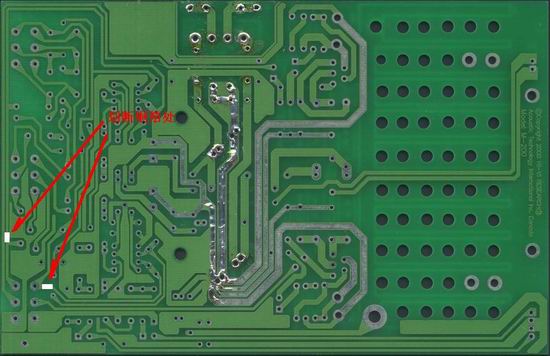
Figure 5
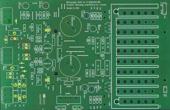
Image 6
See, it's that simple. As long as you are careful, you can succeed, and do n’t forget to try the sound after the change to see how it differs from the original sound. However, I have to say that there is only one level of buffer left in the front stage. At this time, you can change this level to a 10-fold line amplifier to see how it differs from the buffered front stage. There is no need to change the PCB here, just replace the resistance of some resistors. The change is this: R19 is replaced by a 10KΩ resistor, which can increase the input impedance of the circuit, and R13 is replaced by 100KΩ, so that the gain of the front stage = R13 / (R19 + R22) = 100 / (10 + 0.1) ≈ 10 times!
After some of the above, I believe everyone can find some feeling, continue to continue, you can also rub! For the rear stage, you can consider this: remove the feedback DC blocking capacitor, make the circuit DC, widen the frequency response, and improve the low frequency!
Here is the offset voltage of LM1875. The offset voltage of LM1875 is extremely low, which is only ± 1mV, and it is only ± 10mV after LM1875 is amplified by 10 times. Therefore, it is completely feasible to DCize the LM1875, as long as the DC blocking capacitor C26 is short-circuited (see Figure 6 for PCB changes, remove C26, purple is the connecting wire)! In order to prevent the front-end circuit from affecting the LM1875, the coupling capacitor C32 cannot be omitted. As long as the high-quality electrodeless capacitors of 3.3uF-10uF are used, the sound quality can be improved. However, the size of the electrodeless capacitors of this capacity is usually relatively large. It depends on your effort. It is also feasible to use electrolytic capacitors dedicated for audio coupling. It is also possible to adjust the tone according to the characteristics of the capacitor. This is playing capacitors, changing tastes, I do n’t know if you can play this step, haha! When using LM1875, the closed-loop gain of the circuit can be controlled between 10-15 times, and the circuit gain in M-200 K = 1 + R33 / R27 = 1 + 6800/680 = 11 times, so you can change the resistance of R33 To change the gain of the circuit and adjust the circuit to a satisfactory state.
Well, your M-200 can be changed like this, as long as you are careful enough, I believe you will get the effect. Due to the limited knowledge, there are endless articles in the article, hope netizens to correct and discuss!
Soundproof Shangchai Diesel Generator
Soundproof Diesel Generator,Soundproof Shangchai Diesel Generator,Shangchai Soundproof Diesel Generator Set,Soundproof Diesel Generator Set
Jiangsu Lingyu Generator CO.,LTD , https://www.lygenset.com