Looking at the Hi-Fi amplifiers currently on the market, Class A and Class B amplifier products are mostly used for output power above 100W, and Class A amplifier products account for a considerable proportion of 50 to 100W amplifiers. From a high-fidelity point of view, a larger power reserve is of course better, but if it is viewed from the perspective of energy saving, it is worth considering. Because the efficiency of the pure Class A amplifier is very low, while you are enjoying the wonderful music, about 70% or 80% of the electric energy will be dissipated as heat. A pure Class-A power amplifier with 50W output power per channel, if its efficiency is calculated at 30%, the static power consumption is 330W. As a joke, it is simply "watching the stove and eating watermelon." I often encounter this situation when I buy power amplifiers for help people: Although many people are overwhelmed by the sound of pure class A power amplifiers, they often endure the pain because of their "high fever" working status. Large power consumption is also the fatal weakness of the tube amplifier. The market economy is ruthless. Several well-known domestic manufacturers of amplifiers, such as Spark, Ober, and Dajidian, have also launched their own transistor power amplifiers, which proves this point.
According to China's national conditions, the living area of ​​the working class is generally less than 20 square meters, and the living room or bedroom is usually used as a listening room. If the sensitivity of the speaker is above 89dB, the pure Class A power amplifier of 10 ~ 20W can meet the general appreciation requirements. If our ears are exposed to loud sound for a long period of time in an environment like a dance hall, our hearing will gradually decline. Besides, it is not appropriate to quarrel with the neighbors. Therefore, if some power amplifiers with better sound quality and timbre around 15W are produced, and the static power consumption is below 100W, there will definitely be a market. Unfortunately, this type of amplifier is a blank. The Japanese Golden Voice has an A20 with 20W of pure Class A power amplifier per channel. The sound quality is well-known, but the price is prohibitive. Now, domestic manufacturers of power amplifiers seem to be competing. The greater the power, the heavier the weight, but the sales are not very good. Why not make some "delicious and inexpensive" amplifiers to put on the market? In line with this idea, we designed this 15W pure Class A amplifier and tried to make some attempts in this regard.
The schematic part (see Figure 1)
The differential amplifier circuit is composed of VT1 and VT2, and the static current of each tube is about 0.5mA. R3 is the collector load resistance of VT1, and there is direct coupling between VT1 and the driving stage VT4. The output stage consists of two NPN-type high-power transistors VT5 and VT6 of the same model, without the use of complementary symmetric push-pull circuits. The output tube VT6 is a common emitter circuit for the load (speaker), while VT5 is an emitter output circuit, so it is asymmetrically amplified. However, experimental tests show that the open-loop distortion of the entire amplifier circuit when canceling large-loop negative feedback (shorting R5) is very small, and it is mainly even harmonic distortion. This credit should be attributed to the push-level circuit. The driving circuit is the most distinctive circuit of this machine, and its function and effect are better than the traditional RC bootstrap circuit. VT4 is a collector-emitter split-type inverter circuit, which outputs a pair of signals of equal size and opposite directions from its collector and emitter respectively. VT4 is an emitter output circuit for the output tube VT6, and the voltage amplification factor is less than 1. The signal output from the collector of VT4 passes through the light-emitting diode VD1 with a very small AC resistance and is added to the base of the output push tube VT3. The forward voltage drop of VD1 is about 1.9V, which can be regarded as a voltage-stabilizing diode with little noise. It makes the DC voltage UEC across the emitter resistor R7 of VT3 basically unchanged, which is smaller than the voltage-stabilizing value of VD1. 0.7V. For AC signals, R7 is connected in parallel with VT3's launch junction resistance. VT3 and VT5 form the same polarity Darlington composite tube. Therefore, the upper arm of the push-pull amplifier is composed of the first-level common-emitter amplifier circuit (VT4) and the second-level emitter output circuit (VT3, VT5), while the lower arm of the push-pull circuit is composed of the first-level emitter output circuit (VT4) ) And one-stage common-emitter amplifier circuit (VT6), it can be seen that it is an asymmetric push-pull amplifier circuit. Therefore, when selecting an amplification tube, the current amplification factors of these tubes do not have to be matched. This is particularly important when the factory mass-produces, which can greatly reduce costs. The β value of each tube of this prototype is as follows: β1 = β2 = 110, β3 = 50, β4 = 90, β5 = 70, β6 = 90. That is to say, the tubes with a larger β value should be preferentially arranged as VT4 and VT6. The open-loop voltage amplification factor of this power amplifier circuit is about 504, and the closed-loop voltage amplification factor is determined by R4 and R5, which is about 15.7. The theoretical maximum efficiency of the class A push-pull power amplifier circuit is 50%. The effective value of the maximum undistorted output voltage measured by this prototype is 11V, the converted output power is about 15W (8Ω), and the static power consumption is about 40W, so the maximum efficiency is 37.5%. When there is no signal input, the efficiency is zero, and 40W power is almost completely consumed on the two output tubes. Therefore, a radiator with a sufficient area should be added, and the ventilation should be ensured.
In short, the power amplifier has the following characteristics: (1) the current amplification factor of the power output tube does not need to be paired; (2) the push circuit designed by the author replaces the traditional bootstrap circuit, and the frequency response is good; (3) the output voltage amplitude is large ; (4) The circuit is simple, easy to adjust, and easy to make.
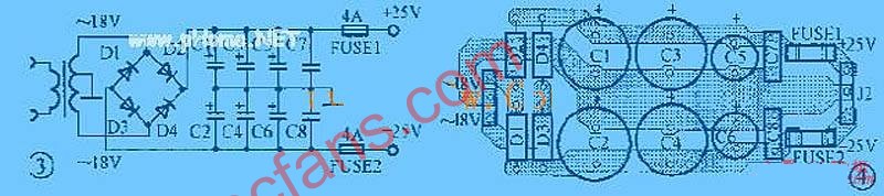
Regulated power supply (see Figure 2)
Because the power amplifier is an OCL circuit and the output is directly coupled to the speaker, a delay protection circuit should generally be installed. However, because the machine uses a ± 17V dual regulated power supply with short circuit protection and soft start function, this part is omitted. Circuit. Both positive and negative voltage regulator circuits use a collector output adjustment circuit, which has high efficiency and short-circuit protection, but it cannot start automatically. VT7 and VT9 form a composite power regulator. VT11 is a sampling amplification tube. Because the base of VT11 is grounded, the emitter potential must be -0.7V to make it work in an amplified state. Therefore, the lower end of R19 cannot be grounded, but connected to -17V. Therefore, if the negative output power supply is short-circuited to ground, the voltage between the emitter and base of VT11 will be zero, so that VT11 will be cut off, so that the adjustment tubes VT9 and VT7 will also be cut off because they cannot get the base current. Make the positive output power supply voltage zero. Since the positive and negative voltage regulator circuits are symmetrical, when the positive power supply is shorted to ground, the negative power supply voltage will also be zero. The reason why the speaker protection circuit is omitted at the output of the power amplifier circuit is that in case of an output tube breakdown and short circuit, the other output tube will not get the power supply voltage due to the above protection function, so that the speaker will not A large DC current will pass through, effectively protecting the speaker.
The output voltage of this power supply is basically determined by the voltage stabilizing values ​​of the two voltage regulators VD4 and VD5, which is about 0.7V lower than their voltage stabilizing values ​​(ie minus the DC voltage drop of the transmitting junction of VT11 and VT12). The two regulator tubes must be carefully selected and matched.
The input filter capacitor uses two 4700μF electrolytic capacitors in parallel on each side, while the output filter capacitor uses only a 10μF non-polar capacitor on each side. Through the actual measurement of the prototype, the ripple voltage when the output current is 2.4A (full load) is very small: the positive power supply side is 0.8mV, and the negative power supply side is 1.25mV. In addition, the waveform is not a sawtooth shape at 100 Hz, but a noise shape with a wide spectrum.
The reason why the voltage stabilizing performance of the power supply is better is that it is because the adjusting tube of the collector output voltage stabilizing circuit has a certain voltage amplification factor, and secondly, because the sampling ratio of the sampling circuit is equal to 1, the voltage change at the output terminal directly passes VD4, VD5 is coupled to the emitters of the sampling amplifiers VT11 and VT12.
In order to eliminate the "pop" sound caused by the inrush current of the speaker when the general OCL circuit is turned on, the power supply has also designed a soft start circuit. The working principle is as follows: After starting, the positive voltage on the filter capacitor C3 charges C5 through R10, and the voltage on C5 rises exponentially. This voltage is added to the output of the positive power supply through R12 and VD2, and at the same time provides current to the emitter of VT12 through R16, so that the negative power supply is also started at the same time. After the power supply voltage reaches the normal value, the positive output voltage provides the trigger voltage to the unidirectional thyristor VD3 through R14 to make it conductive. After VD3 turns on, its anode voltage drops below 0.7V, so diode VD2 turns off. The voltage on C5 is discharged through R12 and VD3. The delay time is determined by the R10 and C5 time constants. In this example, this constant is 0.33 seconds, and there is no sound in the speaker when it is turned on.
The efficiency of the power supply is very high. When the voltage between the collector and the emitter of the adjustment tube drops to 1V, the output voltage can still be stable. If the mains AC voltage is 220V and the input voltage of the voltage stabilizing circuit is set to ± 22V (with rated load), the regulated power supply can still work in the best state when the mains power changes by ± 10%. If the calculated tube voltage drop is 7V, the tube consumption at full load 2.4A is about 17W, so only a small heat sink is needed, and the efficiency is more than 70%. When the voltage drop of the adjusting tube is 3V, the efficiency is 85%.
In short, the power supply circuit features: soft start function; protection function of positive and negative power supply short circuit or short circuit at the same time, which can save the speaker protection circuit; high efficiency, about 70-85%; low ripple coefficient.
Second, the main points of production and adjustment
1. Selection of components Power output tubes VT5 and VT6 use Toshiba's 2SC3281 with β between 70 and 110. In the experiment, Sanken's 2SC 2922 was also used, but it was found that high frequency self-excitation is easy to occur. Push tube VT4 selects NEC's 2SD401, β value is 70 ~ 90, VT3 also uses 2SD401, β is between 50 ~ 70. When the β value of the output tube is above 100, VT3 and VT4 can also use the domestic tube 3DG130 (3DG12). Input stage VT1, VT2 can choose 9012 or 9015, etc., β value is about 100, should not be too high, but matching is required; P-channel junction field effect transistor can also be selected, but the withstand voltage should not be less than 40V (because there is no This type of tube has not been tested). The power of resistors R6, R10 should be selected above 1W, R7, R16, R19 should be selected above 1 / 2W, and the rest are not required. Resistor R9 uses two 1W, 0.51Ω resistors in parallel for sampling. Voltage regulators VD4 and VD5 should be selected with power above 1W. Unidirectional thyristor can choose any model of 1A current.
The VT7 and VT8 of the power supply part use MJ2955 and 2N3055 or other complementary paired tubes, which requires β to be larger, preferably greater than 80. Push tube VT9, VT10 select medium power tube 3CK9, 3DK9, etc., β value is between 50 ~ 80. The sampling amplification tubes VT11 and VT12 use 9014 and 9015, and the β value is greater than 100. Also note that the β values ​​of the corresponding tubes of the positive and negative power supplies should be similar, that is, roughly matched. Capacitors C1, C6, C7 use polyester or polypropylene capacitors. The stabilized power input filter capacitors C3 and C4 use four 4700μF35V high-quality electrolytic capacitors in parallel.
The power capacity of the power transformer should not be less than 100VA, the secondary AC voltage is double 18V, and the current is above 3A. Rectifier can be used 1N5401.
2. Adjustment points
The power supply section requires little adjustment. If the power supply cannot start automatically, the value of R10 should be appropriately reduced, but it should be as large as possible under the premise of being able to start automatically at full load to increase the delay time. The adjustment of the power amplifier part can be summarized into two items; one is to adjust R2 to make the output terminal potential equal to zero; the second is to adjust R6 so that the voltage drop on R9 is equal to 0.3V, and the last-stage quiescent current is about 1.18A. Note that the current can be adjusted to be slightly lower at the beginning, such as 0.9A, and then adjusted to the value specified above after a period of preheating.
3. Circuit modification
The power amplifier circuit can be changed into an OTL circuit with a little modification, and the voltage stabilizing circuit can save the negative power supply part. Although the test results of the OTL circuit are not as good as those of the OCL circuit, the sound is unique. OTL circuit uses output capacitors, although it will affect the frequency characteristics, but the safety of the speaker is guaranteed. Due to space limitations, I will not repeat them here.
3. Main technical indicators
The main technical indicators of the power amplifier are as follows: maximum output power is 15W (8Ω); frequency response is 5Hz ~ 44kHz (-1dB, 10W, 8Ω); voltage gain is 24dB; input sensitivity is 0.7V (rms).
After repeated auditions and comparisons, everyone agreed that when the amp was playing vocals, the voice appeared wide and round, smooth and natural, and could express the singer's emotions very well. The performance of the violin is not frizzy, and the resolution is very high. But for the symphony with a large dynamic range, this power amplifier seems to be a bit powerless, but it feels that the low-frequency volume is relatively moderate, and can outline the contours of various musical instruments. Although it is inferior in large dynamics, because it only has 15W of effective power. Therefore, it is very suitable for family to enjoy music, and has achieved the intended design purpose.

Follow WeChat

Download Audiophile APP

Follow the audiophile class
related suggestion
Avago Introduces New High Linear Power Amplifier Module Product Avago Technologies ...
The circuit is shown in Figure 1. The chip IC uses the LM1875 of the American NS company, which has a soft tone and low distortion (0.015% ...
The word "Monster" has both positive meaning and ...
When the output power of the digital power amplifier is greater than 50W, it is impossible to use only ...
If an "audiophile" is a group of people who are never satisfied with the sound and "loved the new and the old" with the audio equipment. Then just rely on these so-called "fever spirits" ...
First, the circuit principle and characteristics 1. Power amplifier part (see Figure 1)
There is a well-known saying in the Hi-Fi world that is "briefness first." This means that if ...
Simple and practical TDA2822M integrated power
TDA2030 is ...

STK465 thick film ...

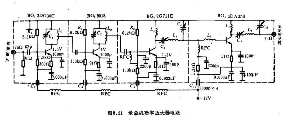
This RF power amplifier can output 2-3 channel signals, covering an area of ​​about one square kilometer, is ...
Transistor DC voltage source
![[Photo] Transistor DC voltage source](http://i.bosscdn.com/blog/20/06/41/5232428729.gif)
![[Photo] 15w RF power amplifier](http://i.bosscdn.com/blog/20/06/41/521040781.gif)
![[Photo] Broadband high frequency power amplifier](http://i.bosscdn.com/blog/20/06/41/520536801.jpg)
Low frequency power amplifier
![[Photo] TDA2030 audio power amplifier](http://i.bosscdn.com/blog/20/06/41/5131012891.gif)
With the newly launched LM4651 and LM465 from National Semiconductor ...
![[Photo] 125W Class D Subwoofer Power Amplifier](http://i.bosscdn.com/blog/20/06/41/513100868.jpg)
![[Photo] Mark Levinson No. 30 ...](http://i.bosscdn.com/blog/20/06/41/513544752.jpg)
EL34 (6CA7) was first launched by Philips in 1956 ...
![[Photo] 45W transistor tube hybrid power amplifier](http://i.bosscdn.com/blog/20/06/41/513531952.jpg)
This article cleverly combines the electronic tube EL34 and the transistor (op amp), ...
![[Photo] 32W hybrid audio power amplifier](http://i.bosscdn.com/blog/20/06/41/513526493.jpg)
The pre-amplifier adopts a European-made TESLA brand low noise high cheek double transistor ...
![[Photo] Gallstone hybrid power amplifier using switching power supply](http://i.bosscdn.com/blog/20/06/41/513524776.gif)
"Simple" means the circuit of the amplifier is simple, making it easier, as long as the picture ...
![[Photo] Simple fool power amplifier](http://i.bosscdn.com/blog/20/06/41/513432946.jpg)
1. Description: & nb ...
![[Photo] LM386 low voltage audio power amplifier ...](http://i.bosscdn.com/blog/20/06/41/513417261.gif)
The Class A transistor power amplifier has a warm and sweet tone, which makes people tempted. But the temperature rise of Class A amplifier ...
![[Photo] Class A power amplifier using SAP15N / P audio pair tube ...](http://i.bosscdn.com/blog/20/06/41/513346769.gif)
The circuit is shown in Figure 5, ...
![[Photo] Using TDA7294 and 2SA1216 / 2S ...](http://i.bosscdn.com/blog/20/06/41/4233420295.gif)
'+ data.data.username +' '; dom + ='
Electric Ceramic Cooktop,Ceramic Surface Cooktop,4 Heating Zone Ceramic Cooktop,4 Burners Gas Cooktop Freestanding
Xunda Science & Technology Group Co.ltd , https://www.xundatec.com