With the improvement of people's requirements for intelligent driving assistance systems and the development of networked automotive electronic systems, the new reversing radar should be able to continuously measure and display the distance of obstacles, and have a communication function to send data to the bus .
In the past, the design of reversing radar used many components and its functions were relatively simple. The reversing radar based on the new high-performance ultra-low power microcontroller MSP430F2274 introduced in this article can make up for the shortcomings of previous products.
Overall system design
The system uses the principle of ultrasonic ranging. Ultrasonic ranging instruments are generally composed of three parts: transmitter, receiver and signal processor. When working, the ultrasonic transmitter sends out ultrasonic pulses, the ultrasonic receiver receives the reflected wave reflected back from the obstacle, accurately measures the time from the transmission of the ultrasonic wave to the reflection of the obstacle, and can calculate the obstacle according to the propagation speed of the ultrasonic distance. As a non-contact detection method, ultrasonic waves have the characteristics of low air propagation attenuation, strong reflection ability and strong penetration. Ultrasonic ranging has the advantages of not being affected by light and rain, snow and fog in a short range, simple structure, convenient production and low cost. High-performance single-chip microcomputer combined with ultrasonic ranging can realize a powerful and convenient parking radar. TI's 16-bit microcontroller MSP430F2274 has extremely low power consumption and abundant on-chip resources. At the same time, JTAG interface technology can be used to easily program on-chip flash memory and software upgrades. It is very suitable as a microcontroller for reversing radar systems. The block diagram of the reversing radar system is shown in Figure 1.
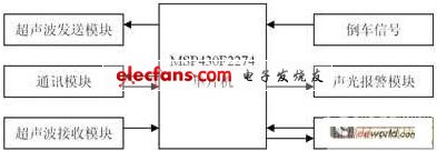
Figure 1 Block diagram of reversing radar system
Hardware system design
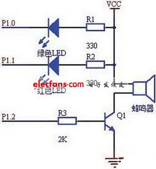
The system takes the MSP430F2274 microcontroller as the core, and the peripheral circuit is composed of five parts: an ultrasonic transmitting circuit, an ultrasonic receiving circuit, an acousto-optic alarm circuit, a communication interface circuit, and a keyboard liquid crystal display circuit, which are introduced one by one below.
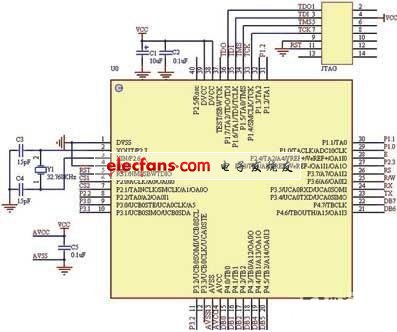
Figure 2 Main control circuit diagram of reversing radar system
The main control circuit diagram of the system is shown as in Fig. 2. The MSP430F2274 selected in this system has 32Kb flash memory and 1Kb RAM, so there is no need to expand the memory. The external 32.768kHz crystal oscillator is used as the clock source for the Basic-TImer in the CPU off state, and it is also used as the system's car clock.
The circuit of the ultrasonic transmission module is shown in Figure 3, which is composed of ultrasonic generation and transmission. There are two methods for generating ultrasonic waves: hardware generation method and software generation method. The commonly used hardware generation method often adopts the following scheme: the ultrasonic wave is generated by the oscillation of the oscillator composed of CD4011, and the ultrasonic transducer is transmitted by the boost conversion, and the start and stop of the oscillator are controlled by the single chip microcomputer. This design uses the software generation method, because the software generation method can not only reduce the complexity of the hardware and reduce the cost of the system, but also has the advantages of strong flexibility, easy implementation, and good stability. This system uses the timer function of the MSP430F2274 microcontroller to generate a stable PWM (40Hz) pulse wave, and outputs it to the ultrasonic transmission part through the I / O port P2.3. In the ultrasonic transmission circuit, the CD4049 includes a total of 6 NOT gates. Only three lines are used in Fig. 3. To prevent interference or electrostatic breakdown, the entire CD4049 is damaged. Get up for grounding. When a series of fixed-frequency pulses are output from the control terminal, a positive frequency and a reverse voltage of fixed frequency are applied to the piezoelectric ceramic ultrasonic transmitting transducer UCM-40-T to emit high-power ultrasonic waves, and the resulting waveform is better than other The effect is more ideal.
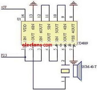
Figure 3 Ultrasonic transmission module of reversing radar
The ultrasonic receiving circuit is shown in Figure 4. This is a difficulty in the design and debugging of this system. Piezoceramic ultrasonic receiver UCM-40-R converts the reflected ultrasonic wave into a voltage signal of 40kHz millivolt level, which needs to be amplified and processed before it can be used to trigger the interruption of the microcontroller. On the one hand, the output signal of the sensor is weak. Due to different reflection conditions, the range of magnification required is about 100 to 5000. On the other hand, the output impedance of the sensor is large, and a multi-stage amplifier circuit with high input impedance is required. . Two schemes are usually adopted: one is to use an operational amplifier to form a multi-level frequency selective amplifier circuit; the other is to use a dedicated integrated preamplifier. The first scheme is prone to self-oscillation, and it is difficult to debug the circuit if the receiving circuit can achieve good sensitivity and anti-interference effect. This system uses a dedicated integrated circuit preamplifier CX20106, which consists of preamplifier, limiting amplifier, band-pass filter, detector, integrator, and integral circuit. The preamplifier has an automatic gain control function, which can ensure that the amplifier has a higher gain when the ultrasonic sensor receives a remote reflection signal and outputs a weak voltage, and the amplifier will not be overloaded when the close-range input signal is strong. Adjust the external resistor R3 of pin 5 of the chip and set the center frequency of its filter to 40 kHz, which achieves a very good effect. When receiving a signal that matches the center frequency of the filter, its output pin 7 outputs a low level, and the output pin 7 is directly connected to P2.2 of the MSP430F2274 to trigger an interrupt.
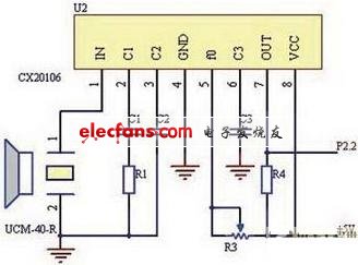
Figure 4 Ultrasonic receiving module of reversing radar
The Mylar Speaker solutions come in a variety of shapes and sizes. We can provide various mounting configurations and performance alterations to fit any industrial application. Our Mylar speakers produce excellent sound output (dB) at specified frequency ranges. The unique characteristics of a Mylar cone allow us to keep tight tolerances during the manufacturing process. Additionally, Mylar is easily and consistently moldable, creating a cost-effective solution, time after time. It`s also beneficial in applications that are exposed to excessive moisture or humidity since Mylar has a high resistance to environmental factors.
Mylar Speaker
Mylar Speaker,Mylar Tweeter,Mylar Cone Speaker,Cellphone Mylar Speaker
Jiangsu Huawha Electronices Co.,Ltd , https://www.hnbuzzer.com