While all products related to medical applications require high reliability, they still need to provide new technologies and functions that end users want. As the competition between medical device companies and their end applications is getting fiercer and the functions are increasing dramatically, another factor that may cause product failure is not considered. All these factors are related to the power supply, and it is important that we need to use the latest technology to minimize the risk.
Smart MOSFET is one of these factors that promote technological progress, and its popularity has increased in value. Because the standard P-channel (P-channel) FET has simple driving requirements, it is often used to switch power distribution nodes, connect charging paths, hot swap connectors, DC current, etc. Because these components are in the critical path, their failure can make downstream sensors or processors useless, so investing in reliable power switches becomes a sensible approach. Compared to the equivalent P-channel / N-channel combination method, Intellimax FETs integrate P-channel FETs and logic-level drivers to easily control this reduced Rdson FET. To increase reliability, these components integrate ESD protection, thermal protection, overcurrent protection, overvoltage protection, and reverse current blocking. All of these bring higher value and higher reliability for medical applications.
The following will introduce the load switch technology and its existing factors in the current power architecture. Its application cases will be presented in the laboratory. We will discuss applications that are less than 6V, and rechargeable portable medical applications should benefit from it. This article will also discuss the new 40V smart FET applications implemented by Fast Semiconductor's latest technological advances, which will provide valuable analysis results and show how smart FETs have become the trend of smart development in the medical industry.
The evolution of load switches in battery applications
Since the introduction of batteries into electronic products, there has always been a demand for power isolation. Importing the battery as a mobile power source means that the battery will be continuously charged and discharged during use. Obviously, the energy-saving features of the design directly affect the time between normal use and charging. In the past few years, battery technology has not seen any substantial improvement, and no major breakthroughs will be seen in the future. Therefore, it is necessary to rely on integrated circuit (IC) technology to comply with strict power consumption specifications to extend the working time of the device.
Before we discuss load switches, we need to examine the battery technology, the load on the battery, and the requirements of the load switch. Under fixed charging conditions, if all current consumption paths are known, it is relatively simple to estimate battery life. A common situation is that a controlled duty cycle sensor with a current of 100 mA does not affect power consumption alone, but many leakage tanks that are less than 1 mA and are always connected are slowly consuming energy. These leakage slots must be roughly added to the power formula, however, it is more difficult that transient peaks can occur when a given function or sensor is enabled. The amplitude and period of these spikes are monitored and used as energy calculations, usually the result of a peak is multiplied by the number of spikes.
After all conventional loads are known, working hours can be calculated directly. At present, the battery is calculated on the scale of mAh, not the previous Coulomb, that is, a 1000mAh battery can provide 1A current for 1 hour or 100mA current for 10 hours at its nominal battery voltage.
Battery working time (h) = battery rating (mAh) ∕ total current consumption (mA)
When the operating current is allocated for 100 ms with inrush current (eg 1500 mA) and the remaining time with continuous current (eg LED indicator of 20 mA), the average current during this period can be linearly calculated.
Average current per hour = (1.5A & TImes; 0.100s / 3600s) + (0.020A & TImes; 3599.9s / 3600s) = 20.04mA
Looking at the concept of power consumption in this domain, you can quickly understand that the load switch can be used to isolate continuous, but smaller current consumption. Short-term sharp pulses are not the culprit. If not isolated, hundreds of uA-level current consumption will reach the mA level. This conversion will bring the importance of soft power ramps, especially when power supplies are used in downstream ICs to reduce undesirable large voltage spikes on fragile mAh battery ratings.
We can independently discuss the impact of surge and stable power consumption. These effects on the battery will vary greatly with the time between battery chemistry and surge power consumption. It is a common belief that a reasonable proportion of surges can bring longer battery life than light and continuous loads. To understand the specific situation in this regard, please consult the battery supplier. It is not discussed that the voltage of the battery pack decreases with the consumption of electric energy. In the above formula based on pure current, we assume that the voltage Vbatt is constant. Moreover, it depends on the technology used by the battery. For alkaline battery (non-rechargeable), Vmax is 1.5V. In most cases, Vmin is assumed to be 0.9V. The nominal state voltage of the rechargeable single-cell Li-ion battery is 3.7V, but it can be charged to a maximum of 4.2V, and it can still fall to the minimum voltage of 2.5 to 3V Vmin, which has a greater impact on the actual charging.
Understanding how the actual current consumption drains the battery level, we can now study different methods to isolate downstream power consumption. The terms high side and low side switches will be used. The high side means that the switch will be in a rail circuit and the current actually flows from the source to the load and returns through the ground circuit. The low-side switch is opposite the load and allows current to flow to the ground circuit.
Applying this simple switching logic to common FET types, Figure 1 shows the performance of basic N-channel and P-channel MOSFETs for load isolation, each with its advantages and disadvantages. Starting from the PN junction cross-sectional image, we can quickly show that the cross-section b has a P-channel on the high side. The N channel is used to drive the gate to simplify logic input control. The disadvantage of the graph B is that if the load voltage is higher than the battery voltage, a forward bias can be applied to the body diode. By using dual P-channel FETs on the high side, the logic diagram c solves this shortcoming, which is a very common battery isolation method for the main level.
Why can't N-channel FETs be used for high-side switches? The characteristic of the N-channel FET textbook is that it can start the switch and make it in the linear region. According to the threshold voltage of the Datasheet, the gate voltage must exceed the leakage voltage. Because the main level in battery applications is usually the highest level available, bootstrap or isolated drive methods must be used. This brings additional cost, however, this N-channel high-side switching method is necessary for larger current applications. Depending on the voltage range, the N-channel Rdson can be reduced by 20-50%. In addition to the losses caused by Rdson, the higher voltage, which is higher than 200V, makes P-channel FETs either expensive or impossible to provide due to technical limitations.
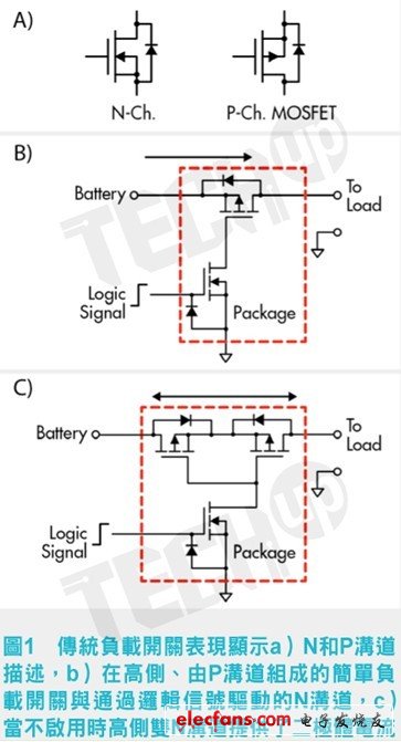
Plate non-damaged desulfator with Smart pulse,Simple and Safe,Save your money, time and worry.
Most of Electric vehicle use lead-acid battery bank(12V /6V /8V cells packed in Series)as the power source. The design lifespan of battery is 2~3 years, but actually the battery is usually failure after 6~12 months used which State-Of-Capacity gradually decline and even some scraped. Through analysis by cutting a large number of failure batteries, the battery water loss and sulfation is quite prominent. Such as the phenomenon of battery sulfation and dehydration can be effectively inhibited to prolong the service life greatly up to 2 times.
Battery Smart Pulse Charging Restorer is a new generation of high-tech products developed specifically for restoring Electric vehicle battery and UPS power system when it is charging every time, it utilizes the energy from the charger, generating electronic smart pulse with special frequency to be resonance with the thick lead sulfate crystals in battery charging process. Under the disturbance by the specific frequency pulse, the recrystallization of lead sulfate can be prevented effectively.
Battery Charger And Restorer 2-in-1 is a multiple-stage charger with smart pulse maintenance ability. This innovative, state-of-the-art battery restorer smartly knows how to restore battery in charging process, Unlike other common chargers on the market, you don't need to select the battery type. It works smartly on any type of 12/24/36/48/60/72-Volt lead-acid battery – VRLA, AGM and flooded. Proprietary algorithms combined with microprocessor & IC controlled technology measure the battery's voltage and current to automatically determine and deliver the precise pulse frequency and duty cycle based on the size and condition of the individual battery.
It is more than a common pulse charger and desulfator. During the restorative battery charging cycle, VoltaTech's patented, optimized frequency pulsing and smartly changeable duty cycle constantly work to minimize and reduce battery sulfation and internal resistance. By reducing the size and number of lead sulfate deposits on the battery plates- the No.1 cause of battery failures, increase capacity and release energy to keep battery in new conditions, your battery will charge deeper, maintain greater reserve capacity and last longer service lifespan– up to 2 times longer.
Battery Smart Pulse Charging Restorer
Battery Smart Pulse Charging Restorer,Battery Charger Restorer,Smart Battery Charger,Deep Cycle Battery Charger
Shenzhen Daceen Technology Co., Ltd. , https://www.daceen-sz.com