1 Introduction
USB3.0 is a high-speed, serial, source-synchronous data transfer protocol. However, the data deviated greatly from the original data through the transmission line. This article analyzes the elastic buffer mechanism from the perspective of USB3.0 , explains the difference from other designs, and uses pointer control and handshake design methods to achieve.
2. Elastic cushioning
2.1 USB3.0 flexible buffer scope
In USB3.0, data transmission adopts double simplex, so the physical layer is designed to receive and send two sets of differential pair transmission parts. The transmission line is a carrier that carries data transmission. Therefore, how to correctly receive data from the transmission line and synchronize it to the internal clock domain of the system becomes very critical.
The structure diagram of the physical layer receiving part specified in USB3.0 is as follows. It includes differential receiving, clock data recovery, serial-to-parallel conversion and 8B10B decoding.
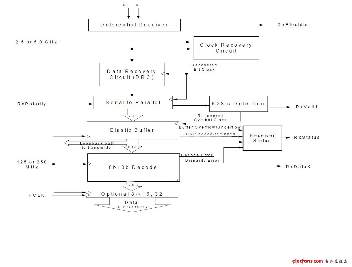
Figure 1 USB3.0 physical layer receiving part structure
The whole data flows from top to bottom, the differential input undergoes differential reception, extracts the clock from the differential signal, and uses the recovered clock to recover the data (CDR). The recovered data is serial-to-parallel converted to 10-bit wide parallel data 1 in the receiving clock domain, and the USB3.0 packet start indicator (K28.5) is detected. Once the start marker K28.5 is detected, the enable symbol is valid (symbol lock), and the end symbol is valid until the end symbol is detected.
The elastic buffer converts the received data from serial to parallel, all the received data and control work in the receive clock domain (receive clock). Therefore, the elastic buffer must synchronize data and control to the system clock domain (system clock). Pass the data down to the 8B10B decoding module, and then pass it to the system.
2.2 Flexible buffer capacity
In USB3.0, the agreement stipulates that the allowed clock precision is -5300ppm to 300ppm. The symbol clock frequency is 2ns or 2000ps. In the worst case, one SKP is added or deleted every 178 symbols, that is, one SKP pair (SKP Order Sets) is added or deleted every 356 symbols. The maximum length of a packet in USB3.0 is 1052 bytes, so in the worst case, up to 8 SKPs or 4 SKP pairs can be added or deleted, so the elastic buffer must be able to buffer at least 8 SKPs. The USB3.0 protocol specifies that each SKP order set is 2 consecutive SKP symbols. Therefore, before 10B8B decoding, the running disparity of the SKP order set should be complementary.
Through calculation, the buffer capacity of the elastic buffer is 8. In this paper, the design uses the normal half full 2 ​​(normal half full) mode to design the elastic buffer, so the elastic buffer capacity is 16, under normal circumstances there should be 8 data, the remaining 8 are buffer space, so it is called normal half full . Normally half full mode first writes 8 symbols to the buffer to reach half full, and then the read enable can be effective, so there is a delay of about 8 clocks. Normally half full mode can only add or delete SKP pairs if they appear in the symbol queue. The following figure is the timing diagram of constant half full input and output.
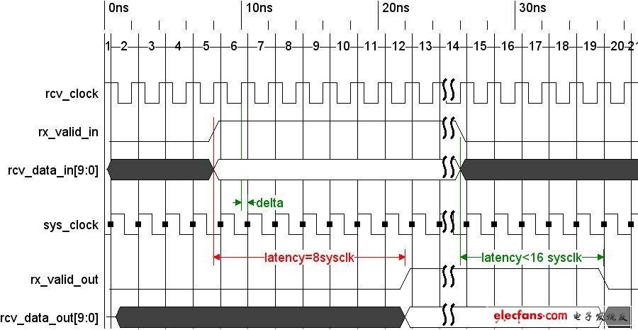
Figure 2 Constant half full input and output timing
As can be seen from the above figure, rx_valid_out is valid about 8 clock edges later than rx_valid_in; invalid is about 0 to 16 clock edges later than rx_valid_out (depending on poor clock accuracy). Therefore, it usually takes 8 clock delays to output data at half full.
2.3 Elastic buffer mechanism
The elastic buffer is essentially an asynchronous FIFO with simultaneous read and write control. A normal half full FIFO has a depth of 16, and first writes 8 valid data and maintains it in a half full state. Therefore, under normal circumstances, the FIFO has been at or near half full, and when the read and write clocks are as fast as slow, there are 8 valid data in the FIFO.

Figure 3 Always half full read and write at the same rate
When the read clock is faster than the write clock, more data is read than written data, often half full mode may result in less than 8 data in the FIFO, and may even be read empty. As shown in the figure below, when the SKP window appears, the valid data in the FIFO is 4, which is 4 less than normal. Therefore, at this time, the elastic buffer should add 4 SKPs to keep the FIFO half full to adjust the clock. At this time, the read pointer jumps forward by 4 intervals, and when the read pointer reads the skip interval, SKP addition is completed.

Figure 4 Always half full mode read faster than write
When the read clock is slower than the write clock, more data is written than read data, often half full mode may result in more than 8 data in the FIFO, and may even be full. As shown in the figure below, when the SKP window appears, the effective data in the FIFO is 10, which is 2 more than normal. Therefore, at this time, the elastic buffer should delete 2 SKPs to keep the FIFO half full to adjust the clock. At this time, the write pointer should pause for 2 clock cycles to complete SKP deletion.
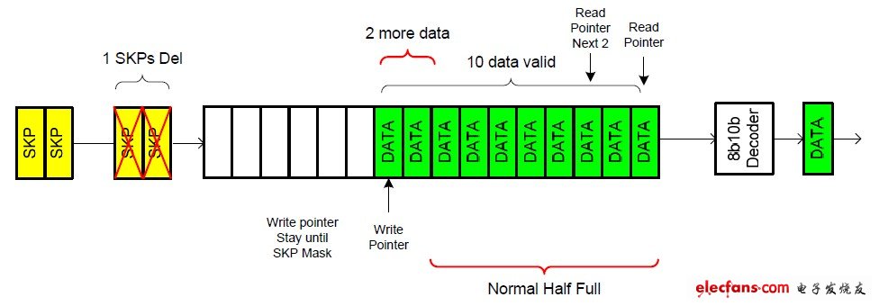
Figure 5 Often half-full writing is faster than reading
VESA (physical installation interface for Video Electronics Standards Association flat panel display) mounting holes are reserved on the back. Through VESA, a variety of mounting methods such as wall mounts, brackets, and swing arms can be formed. The front panel meets NEMA / IP65 waterproof and dustproof standards, preventing installation in When the control cabinet is splashed with water droplets and steam entering the host, it affects the operation of the equipment; The high-strength all-steel box structure makes it suitable for the harsh working environment of industrial sites, and is most suitable for factory automation, machinery manufacturing, numerical control equipment, Textile equipment, communication network, electric power automation and other industrial occasions.
Wall Mount Vesa Monitor,Wall Mounted Touch Screen,Wall Mounted Touch Screen Display,Wall Mount Touch Screen Monitor
Shenzhen Hengstar Technology Co., Ltd. , https://www.angeltondal.com