2, the brightness is not the same (16s is less than 8s less than 4s);
3, the price is not the same, or understand the number of driver ICs used is not the same (the same model 16s is lower than 8s less than 4s)
At present, the display screens on the market can be roughly divided into static scanning and dynamic scanning! Static scanning is divided into static real pixels and static virtual! Dynamic scanning is also divided into dynamic real image and dynamic virtual `` respectively, 2 sweep, 4 sweep, 8 sweep, 16 sweep ``
List of instructions: A commonly used full-color module: The pixel is 16*8 (2R1G1B) MBI5026 driver, the total lamp used by the module is: 16*8*(2+1+1)=512, MBI5026 is 16-bit chip !
(1) 512/16=32, if it is 32 MBI5026 chips, this board is static virtual
(2) If two red lights are connected in series on the board, use 24 MBI5026 chips, which are static real pixels.
(3) 12 MBI5026 chips, dynamic 2 sweeping pixels
(4) 16 MBI5026 chips, dynamic 2 sweep virtual
(5) 8 MBI5026 chips, dynamic 4 sweep virtual
(6) 6 MBI5026 chips, dynamic 4 sweeping pixels
V represents the voltage.
F stands for positive.
I represents current.
R stands for reverse.
WL stands for wavelength.
Therefore: VF stands for forward voltage. Generally, the vf of red, yellow, orange and yellow green is 1.8-2.4v, and the vf of pure green, blue and white is 3.0-3.6v. IF is the forward current, and the IF of the small power LED is 20mA. IR is the reverse current,
Generally measured under the reverse voltage of 5v, the fraction is less than 10uA (microamperes), less than 5uA and 0uA several grades. WL is the wavelength of light. The visible light has its own wavelength. Different wavelengths correspond to different colors. For example, red light is generally 615-650 nm (nanometer), and blue light is generally 450-475 nm. White light is modulated by blue chip + phosphor, so there is no wavelength, measured by color temperature (yellow below 3000k, 3000k-7000k white, 7000k or more blue).
What does the Vf value of the LED mean? How does its size affect the LED?
Vf is the meaning of the forward voltage, but the larger the forward voltage, the larger the forward current. You see that as long as it is a small power led acknowledgment book will have a vf value, there is an If value, no matter how large the vf value, (red, yellow, yellow green, orange is generally 1.8v-2.4v, white, blue, green Generally 3.0v-3.6v). If both are 20mA. The two are complementary. For example, 2 white light, one is 3.0v, 20mA, one is 3.4v, 20mA, which means the first light, you give it 3.0v voltage, the current flowing through it is the normal rated current 20mA, but the first For two lights, you have to give it a voltage of 3.4v, and the current flowing through it is 20mA. Here Vf and If are not directly proportional; but a yellow light and a white light, such as the yellow light voltage is 2.0v, the white light voltage is 3.3v, this yellow light is at 2.0v voltage and this The white light flows through them at the voltage of 3.3v. The current is the same, both 20mA, where Vf and If are not proportional. Therefore, Vf and If are absolutely proportional to the case of the same lamp. When you use it, no matter how big the Vf is, just control the current flowing through all the lamps to 20mA.
LED basic term luminous flux (lm): The sum of the amount of visible light emitted by the light source per second. For example, a 100 watt (w) bulb can produce 1500 lm, and a 40 watt (w) fluorescent lamp can produce 3500 lm of luminous flux. â—‡ Luminous intensity (cd): The luminous flux emitted by a light source in a unit solid angle, that is, the density of the luminous flux emitted by a light source in a spatially selected direction. The unit of light intensity is Cantra (cd), also known as candlelight. For example, 1 lumen of light emitted in a unit of three-dimensional angle is called 1 Cantera (1 cd). â—‡ Brightness: LED is a kind of illuminating device. Brightness refers to the illuminance per unit area. The unit is: candle/square meter, and the standard driving current of LED is 20mA.
Color temperature (k): expressed in absolute temperature (k=°C+273.15)K, that is, a black body is heated, and when the temperature rises to a certain extent, the color gradually becomes dark red-light red-orange-yellow-yellow-white-white-blue-white - Blue changes. When the color of a light source is the same as that of a black body, we refer to the absolute temperature of the black body at that time as the color temperature of the light source. For example, when the black body is heated to a deep red, the temperature is about 550 ° C, that is, the color temperature is 823 K.
Light efficiency (lm/w): The luminous flux emitted by the source divided by the power consumed by the source. It is an important indicator of energy saving in light sources.
Color rendering (ra): The degree to which a light source appears to the color of an object itself is called color rendering. That is the degree of realism of the color. The International Commission on Illumination CIE sets the sun's color rendering index to 100. The color rendering indices of various types of light sources vary. Such as: incandescent lamp ra ≥ 90, fluorescent lamp ra = 60 ∽ 90.
Viewing angle: Angle is divided into X axis (left and right) Y axis (upper and lower). When the center axis is 1 brightness, the left and right or up and down axis brightness is 1/2, the angle is the viewing angle; for example, 70 ° can be used. The viewing angle refers to 35 ° from the center point up and down or left and right.
Wavelength: the wavelength of the light emitted by the diode, generally red wavelength is 620-660nm, pure green 520-530nm, blue 470-480nm, yellow 580-890nm, yellow green 550-570nm, please refer to the chromaticity diagram, different The wavelength of the emitted light is different; the mixing of the two colors is different.
Quaternary system: A light-emitting diode made of four chemical elements of ALInGaP, which emits light between yellow-green/yellow/orange/red (wavelength 550-630nm), with high brightness and low attenuation. At present, the mainstream products of outdoor light-emitting diodes.
Pure green/yellow green: The traditional green LED is mainly yellow-green, with wavelengths from 550-570nm, low price, low brightness and fast decay. In 1994, Japan's Asian manufacturing company produced pure green (wavelength 520-530nm) price. High, high brightness, slow decay, widely used on outdoor displays, these two products have great differences, and must be clearly distinguished when designing.
Monochrome/double primary color/full color screen: the three primary colors are red/green/blue; if one of the three LEDs is included in one pixel tube, it is called full color display; if only red + green is called double primary color screen, If there is only one color such as red or yellow, it is called monochrome display, the monochrome display is mainly for playing pure text content, the double primary color is mainly for text + pattern + animation, and the full color screen is mainly for broadcasting video signals. .
Service life: refers to the time when the brightness of the LED reaches half of the initial value, and it becomes a half-life. Different chips will have different service life in different environments.
Luminance attenuation curve: The curve of brightness and time of various chips under certain conditions (temperature, current); this curve can really understand the characteristics of the chip.
Chip/single lamp/pixel tube: The diode lamp is a semiconductor material, and its light-emitting component is called a chip. The chip is packaged into a single unit lamp that can be illuminated; many small lamp assembly glues are packaged into a large tube. Add the cover to the pixel tube.
Point diameter: refers to the diameter of the pixel tube.
Point spacing: refers to the distance between the centers of two adjacent pixel tubes. The standard distinguishable lamp point spacing = lamp point diameter × 1.25.
Visible distance: It means that the content displayed on the display body can be clearly seen at this distance. This distance is related to the height of the displayed text. Simple calculation formula: --- Nearest visible distance: 50 × height (m) ---The farthest visible distance: 200 words height (m)
Automatic brightness adjustment: LEDs adjust their own brightness according to the intensity of the ambient brightness. Generally, the method of reducing the current is used to reduce the brightness.
Point density: refers to how many pixel tubes per square meter.
Operating temperature: The lowest temperature and highest temperature at which the display can be used normally.
Comparison of LED light source and traditional light source Light source type (lm/w) Color temperature (k) Average life (hours)
Incandescent light bulb 15 2800 1000
White British halogen lamp 25 3000 2000-3000
Ordinary fluorescent lamp 70 full range 8000
Three primary color fluorescent lamps 96 full range 10000
LED light 50-250 full range 50000
Explanation of several optical terms of LED and conversion relationship 1. What is the meaning of luminous intensity (luminosity)?
Answer: Luminous intensity (luminosity, I) is defined as: the luminous intensity of a point source in a certain direction, that is, the amount of light emitted by the illuminant per unit time, also referred to as luminosity, commonly used in candlelight (cd, candela), An international candlelight is defined as a luminosity of 120 grams of grain burned per hour from a candle made of whale fat, equal to 0.0648 grams.
2. What is the unit of luminous intensity (luminance)?
A: The common unit of luminous intensity is candlelight (cd, candela), and the international standard candlelight (lcd) is defined as the ideal blackbody at the platinum freezing point temperature (1769 ° C), perpendicular to the black body (its surface area is 1 m2) in the direction of 600,000 points One of the luminosity, the so-called ideal black body means that the emissivity of the object is equal to 1, the energy absorbed by the object can be completely radiated, so that the temperature is kept evenly fixed, and the international standard candle (candela) is interchanged with the old standard candle (candle). The relationship is 1candela=0.981candle
3. What is luminous flux? What is the unit of luminous flux?
A: The luminous flux (φ) is defined as the energy emitted by a point source or a non-point source in a unit of time. The radiant flux that can be perceived by a person (the radiant flux that a person can perceive) is called luminous flux. The unit of luminous flux is lumens (abbreviation lm), and lumens (lumen or lm) are defined as the luminous flux of a light source of an international standard candle passing through a unit solid arc angle. Since the entire spherical area is 4πR2, the first-class bright luminous flux is equal to one candle. The 1/4 π of the emitted light flux, or the spherical surface has 4π, so according to the definition of lumens, a point source of cd will radiate 4π lumens, that is, φ (lumen) = 4πI (candle), assuming that ΔΩ is a small solid arc Angle, in the △ Ω solid angle luminous flux △ φ, then △ φ = △ Ω I
4. What is the meaning of one foot candlelight?
A: One foot of candlelight refers to the illuminance on a face that is one foot away from a light source (point or non-point source) and orthogonal to the light, abbreviated as 1ftc (1lm/ft2, lumens/ft2), ie The luminous flux received within a square foot is 1 lumen, and 1ftc = 10.76lux
5. What is the meaning of one meter candle?
A: One meter of candle light refers to the illuminance on a surface that is one meter away from a light source (point source or non-point source) and orthogonal to the light. It is called lux (also written as lx), that is, per square meter. The luminous flux received within the lumen is 1 lumens (lumen/m2)
What is the meaning of 6.1lux?
A: The luminous flux received per square meter is 1 lumens of illumination.
7. What is the meaning of illuminance?
A: Illuminance (E) is defined as the luminous flux received by the illuminated area of ​​the object, or the luminosity of the object illuminated by light per unit area per unit of time, in meters of candlelight or foot-candle ( Ftc)
8. What is the relationship between illuminance and luminosity and distance?
A: The relationship between illuminance and luminosity and distance is: E (illuminance) = I (luminosity) / r2 (distance square)
9. What are the factors related to the illumination of the subject?
A: The illumination of the subject is related to the luminous intensity of the light source and the distance between the subject and the light source, regardless of the color, surface properties and surface area of ​​the subject.
3. The role of each IC of the display unit
Display unit board components:
The driver chip is mainly 74HC595 74HC245/244 74HC138 4953.
The role of 74HC245: signal power amplification
The unit board/module is connected in series by multiple blocks, and the control signal is relatively weak, and its power needs to be amplified during signal transmission.

The first pin DIR is used for input/output port conversion. When DIR=“1†high level, the signal is output by “A†terminal input “B†terminal. When DIR=“0†low level, the signal is input from “B†terminal. "End output.
The second to the 9th "A" signal input and output terminals, A1 = B1,,,,,, A8 = B8, A1 and B1 are a group, if DIR = "1" G = "0", then A1 input B1 output, Other similar. If DIR = "0" G = "0", B1 inputs A1 output, and the others are similar.
The "B" signal input and output terminals of the 11th to 18th feet have the same function as the "A" end and will not be described.
The 19th pin G, the enable terminal, if the pin is "1", the signal of the A/B terminal will not be turned on. When only the "0" is enabled, the A/B terminal is enabled, and the pin acts as a switch.
Pin 10 GND, power ground.
The 20th foot VCC, the power supply is positive.
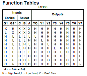
The role of 74HC138: eight-bit binary decoder
The 74HC138 is used to select the display line. A 74HC138 can select one of the 8 lines, so there are 2 74HC138 on the unit board/module, so that one line can be selected in the 16 lines.

Pin 8 GND, power ground.
Pin 15 VCC, positive power supply
Pins 1~3 A, B, C, binary input pins.
The 4th to 6th chip select signal control, only when the 4th and 5th feet are "0" and the 6th pin is "1", it will be strobed, and the output is controlled by the A, B, C signals. Any other combination will not be strobed, and the Y0~Y7 outputs are all "1".
It is cascaded by controlling the strobe pin to extend it to sixteen bits.
Example: G2A=0, G2B=0, G1=1, A=1, B=0, C=0, then Y0 is “0†Y1~Y7 is “1â€, see the truth table for details.
The role of 74HC595: LED driver chip, 8-bit shift latch
Used to drive the display column, each 74HC595 can drive 8 columns, multiple 74HC595 are connected in series, serial column data signal RI (DATA), latch signal STB, serial clock signal CLK are all on this chip.
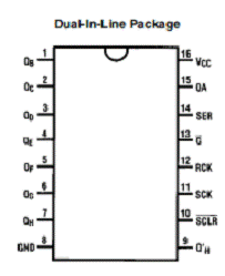
Pin 8 GND, power ground.
16th pin VCC, positive power supply
The 14th pin DATA, the serial data input port, the display data is entered by this, and must be matched by the clock signal to be moved in.
Pin 13 EN, enable port, when the pin is "1", the QA~QH ports are all "1". When it is "0", the output of QA~QH is controlled by the input data.
The 12th pin STB, the latch port, when the input data is in the incoming register, only the input of a latch signal can send the moved data to the QA~QH port.
Pin 11 CLK, clock port, each clock signal will move a bit of data into the register.
The 10th pin SCLR, reset port, as long as there is a reset signal, the data moved in the register will be cleared, the display does not need this pin, generally connected to VCC.
Pin 9 DOUT, serial data output, passes the data to the next one.
The 15th, 1~7 feet, the parallel output port is also the drive output port, driving the LED.
The role of 4953: row drive tube, power tube
The current required for each display line is relatively large. To use the row driver tube, each chip can drive 2 display lines.
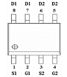

The inside is two CMOS tubes, 1, 3 pin VCC, 2, 4 pin control pin, 2 pin control 7, 8 pin output, 4 pin control 5, 6 pin output, only when 2, 4 feet are "0 When, 7, 8, 5, and 6 will output, otherwise the output will be in a high impedance state.
The role of TB62726: LED driver chip, 16-bit shift latch
Some cell boards/modules use the TB62726 instead of the 74HC595, and one TB62726 can drive 16 columns. That's it.
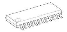
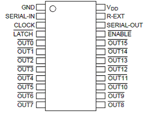
Pin 1 GND, power ground.
Pin 24 VCC, positive power supply
Pin 2 DATA, serial data input
Pin 3 CLK, clock input
Pin 4 STB, latch input
Pin 23 output current adjustment terminal, connection resistance adjustment
Pin 22 DOUT, serial data output
Pin 21 EN, enable input
Other functions are similar to those of the 74HC595, except that the TB62726 is a 16-bit shift latch with output current adjustment, but there is no high level on the parallel output, only the high-impedance state and the low state. The 74HC595 parallel output has high and low outputs. The TB62726 has the same pin function as the 5026 and is similar in structure.
4. The number of LED unit boards with each power supply
Number of currents per power supply X Number of scans / Number of cells in the cell row / Number of pixels in the cell column / Number of colors per pixel (or total number of LEDs per pixel) / Number of cells per LED = Number of cell boards
16-sweep double-primary 64*32 dot matrix common cell board (5. 0 and 3.75 are the same). With 40A power supply, the number of unit boards that can be driven is as follows:
Cell board row pixels = 32
Unit board column number of pixels = 64
Number of colors per pixel = 2
Number of currents per LED = 0.01A ~ 0.02A
= 40 * 16 / 32 / 64 / 2 / 0.01 = 15
= 40 * 16 / 32 / 64 / 2 / 0.02 = 7.5
4 Scan monochrome 64*64 point outdoor box, 2 red LEDs per pixel as an example. With 40A power supply, the number of unit boxes that can be driven is as follows:
Unit box row pixels = 32
Unit box column number of pixels = 64
Total number of LEDs per pixel = 2
Number of currents per LED = 0.01A ~ 0.02A
= 40 * 4 / 64 / 64 / 2 / 0.02 = 1 block
The number of currents of each luminous tube is boldly selected from 0.01, and some conservatively selected 0.02, 10~20mA are normal. Who knows how many units of each manufacturer are designed according to the number of tubes. Some have no current limiting resistors, which may be more than 50mA. It is very easy to burn the tube.
Another common method is to have two cell boards in the test mode, let it be fully lit, and the multimeter measures the DC current. It is possible to calculate the number of cell boards per power supply.
Also consider the true ability of the power supply, some power supply is said to be 40A, the actual is fake, can not do. The specific test method is to bring a few unit boards, or the corresponding load, 50% of the output, it should not heat within 10 minutes.

First, the module signal introduction |
Electric Fan is a home appliance driven by an electric motor through the blades rotary, promote air accelerate circulation, mainly used to cool the hot weather and circulation of air. The electric fan is easy to install, dismantle and move. Electric fan is widely used in homes and public places. Our factory produce and sale stand electric fan, wall electric fan, table electric fan and bladeless electric fan, etc. Our electric fan`s pure copper motor with high quality reinforced Silicon steel sheet and new enameled wire, higher magnetic permeability, less power attenuation, more power, more stability, longer life, more energy-saving; The electric fan`s motor optimization technology applied, motor temp rise less than 65k when full loading, with over heat protection, more safety; The electric fan`s blades adopt new AS material, more stablility, more power, more wind, no deformation, no broken, anti-aging.
Electric Stand Fan, Portable Electric Fans, Wall Mount Electric Fans, Industrial Electric Fan
Ningbo APG Machine(appliance)Co.,Ltd , http://www.apgelectrical.com