This paper introduces the design of the structure and function modules of the multi-function embedded vehicle travel monitoring terminal based on LPC2292 and μClinux system; analyzes the hardware and software parts of the system design in detail, and details the establishment of the driver in the embedded system. discuss. The monitoring terminal can monitor all kinds of performance parameters of the vehicle in an all-round way, and use the bus interface as a vehicle in-service maintenance and diagnosis tool; combined with the wireless communication module, an all-round monitoring system of the remote vehicle can be established to improve the vehicle management level.
Keywords embedded system vehicle monitoring CAN driver CTM8251 TJA1020
This article refers to the address: http://
1 Terminal function In addition to the accident analysis function possessed by the traditional recorder, the monitoring terminal can also issue an overspeed alarm sound when the driver is overspeeding to remind the driver to decelerate and record the vehicle's driving time in detail. , mileage, driving time, maximum speed, and duration of each maximum speed, convenient traffic management department to effectively manage the vehicle according to the recorded data; at the same time, the equipment can realize a variety of information processing, showing the status of the vehicle Self-diagnosis, effective monitoring of a series of parameters such as vehicle speed, engine speed, water temperature, oil pressure, brake pressure, tire pressure and battery voltage; by controlling LEDs, liquid crystal display, buzzer and other alarm means, for the driver Personnel provide direct information on the condition of the vehicle and issue various alarms such as over-limit conditions, which can effectively prevent and resolve the occurrence of vehicle accidents. In addition, the terminal has GPRS and GPS modules, which can transmit various monitoring data to the company management center in real time, which facilitates the unified scheduling and driving monitoring of the company's vehicles, which is conducive to improving the company's management level.
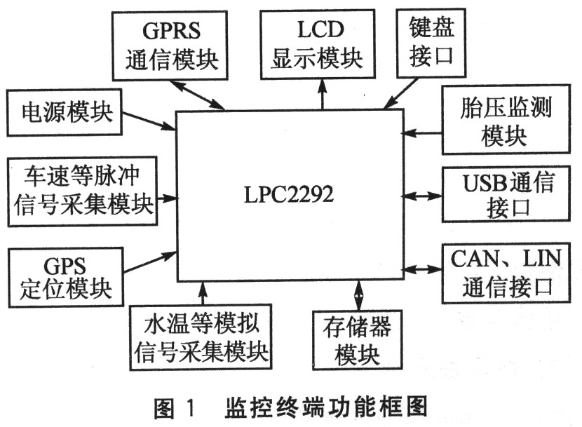
2 Terminal function module design uses LPC2292 microcontroller with ARM7TDMI-S core, which can realize the collection, processing and real-time storage of analog signals such as vehicle speed, speed signal, switch signal and water temperature, brake pressure and tire pressure. And display, through the serial port, USB interface can achieve data communication with the PC, through the CAN and LIN bus interface can achieve data communication with the CAN or LIN node on the car. The peripheral interface module of the system includes power module, vehicle speed and other pulse signal acquisition module, water temperature and other analog signal acquisition module, keyboard interface module, memory module, GPS positioning module, GPRS communication module, LCD display module, tire pressure monitoring and communication interface module. The block diagram of the system is shown in Figure 1. Due to space limitations, this article only analyzes the design of several feature modules.
2.1 Vehicle speed and speed signal acquisition circuit design The existing transport vehicles are generally equipped with Hall-type integrated sensors. The voltage signal converted into vehicle speed is sent directly to the speedometer. The signal acquisition is convenient. The specific processing method is directly from the speedometer. The terminal block obtains the vehicle speed signal. The specific wiring method is determined according to the speedometer signal output circuit. The signal is sent out to the optocoupler 4N35 high-speed isolation switch, and then sent to the integrated operational amplifier LM358D front differential circuit to further remove the interference and effectively amplify. The output of the LM358D (7-pin) is sent to 9013 for secondary amplification. The vehicle speed signal is a square wave signal with a duty cycle of 50%, and the clutter has been removed, which can be directly sent to the timing capture port of the microcontroller for counting. The specific circuit is shown in Figure 2. After repeated experiment optimization, the circuit has strong anti-interference ability. The real vehicle test can detect the speed signal stably and accurately regardless of the low speed state or the vehicle speed exceeding 110 km/h. Similarly, the engine speed signal can be processed in a similar way (not repeated here).

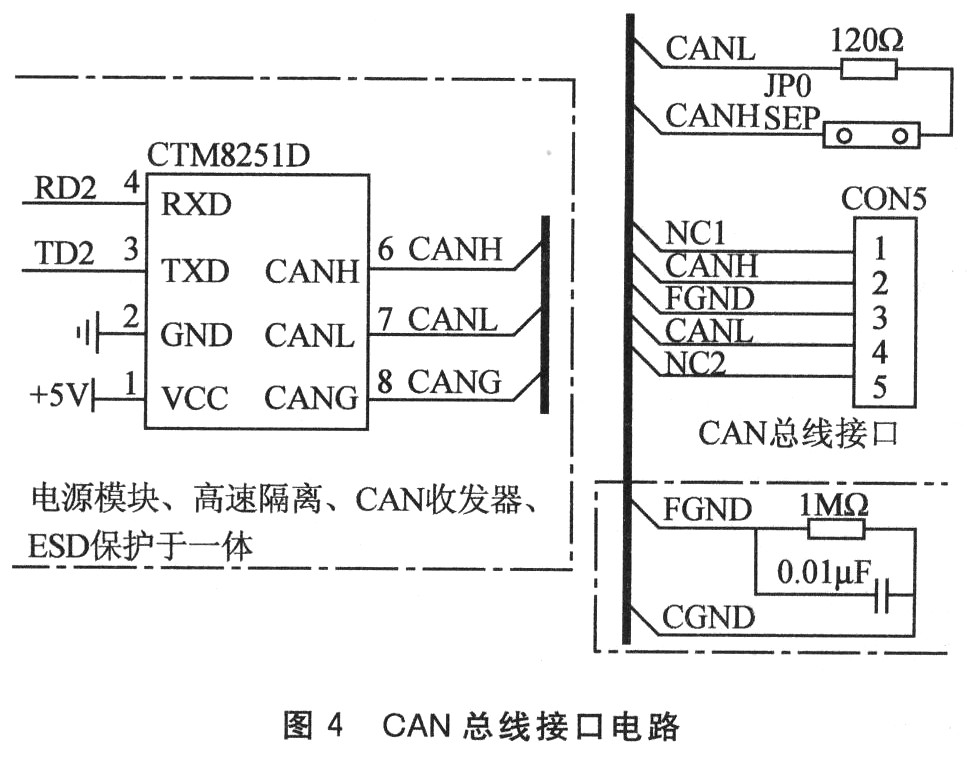
2.3 CAN bus interface function design CAN needs to have CAN controller and CAN bus driver for normal work. The former implements the functions of the data link layer and the physical layer in the network hierarchy, while the latter provides the interface between the CAN controller and the physical bus and the differential transmission and reception functions to the CAN bus. The LPC2292 microcontroller contains two CAN controllers with data rates up to 1 Mbps on a single bus, 32-bit registers and RAM access with global filters and acceptance filters. This system adopts CTM8251D dual-channel isolated CAN transceiver, which can connect at least 110 nodes. By extending the CAN bus interface, the choice of serial communication mode is more diversified. When the in-vehicle instrument also has a CAN bus interface, they can directly use this interface to communicate with the recorder. The CAN bus interface circuit is shown in Figure 4.
CAN communication is similar to general serial communication. Before the data communication, the CAN bus should be initialized, including the selection of the CAN controller, the setting of the data register, and the setting of the communication baud rate. After the initialization is complete, you need to set up the communication protocol between the two parties to establish a connection with each other. Only parties working under the same agreement can exchange data correctly. The CAN communication protocol set by this system is: no filter condition, bypass mode, baud rate can be preset.
The CAN-BUS communication function interface provided by this system is as follows:
1 Initialize CAN: int CAN_Init(int cannum, uint32volatile baudset).
Function entry parameter: cannum is the selection identifier of the CAN controller. The CAN0 controller is selected for 1 and the CAN1 controller is selected for 2; baudset is the baud rate and can be preset.
Function exit parameter: 0 is returned when the initialization succeeds, and 1 is returned if it fails.
Function: Initialize the CAN controller.
2CAN bus sends data: int CAN_SendData (int can-num, uint32 volatile frameinfo, uint32 volatile senddatal, uint32 volatile senddata2, uint32 volatile canmode).
Function entry parameters: cannum as above; frameinfo is frame information, used to set the frame information register; senddata1 and senddata2 are the data to be sent, respectively, used to set data registers A and B; canmode is used to set the CAN working mode.
Function exit parameter: 0 is sent successfully, and 1 is returned if it fails.
Function: CAN bus for data transmission.
The 3CAN bus receives data: int CAN_RcvData (int can-num.uint32 volatile *pdatal, uint32 volatile *pdata2). Function entry parameters: cannum is the same as above; pdata1 and pdata2 are the receive data pointers.
Function: The CAN bus receives data and reads the data into the corresponding pointer from the data registers CANRDA and CANRDB.
2.4 LIN bus interface circuit design LIN is a vehicle communication protocol standard in low-cost network, which can improve communication quality and reduce cost. It will be an important factor in the use of car grading network in automobiles. The LIN bus is a simple single bus system with a simple software stack. A LIN network consists of a host node and more than one slave node. All nodes include a slave service program to send and receive data. Only one node contains a host server. The host program is mainly used to send synchronization intervals, synchronization fields and ID fields (or commands) to control and coordinate the orderly communication of each node.
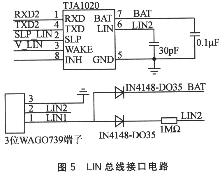
The LPC2292 microcontroller integrates the necessary hardware to implement the LIN bus node, including the UART, capture input, and enough timers, especially its capture input capability, which provides great support for LIN's frame header recognition, frame synchronization & baud rate measurements. Convenience. LIN bus interface circuit shown in Figure 5, mainly composed of LIN physical layer interface chip TJA1020, connected with LPC2292 serial port 2, which mainly completes the mutual conversion between MCU communication signal and LIN physical bus signal, provides a MCU with LIN physics The interface of the bus.
2.5 Infrared Universal Interface Module For the purpose of user uniform data collection, the system has designed a universal infrared interface. It supports infrared remote control and data communication, supports the IrDA protocol, and can easily communicate with a variety of devices that comply with the protocol standard. The module consists of HSDL7001 codec chip and HSDL3600 infrared transceiver chip. The HSDL7001 is connected to the serial port of the MCU. The block diagram is shown in Figure 6.
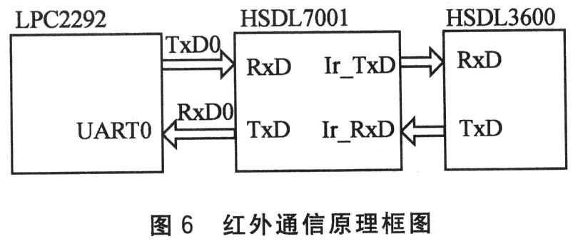
The HSDL7001 drives IrDA-compatible transceivers with a maximum transfer rate of 11 502 kbps. It has an internal SIR encoder and an SIR decoder. It supports both internal (external 3.684 MHz crystal) and external 16XCLK input modes. When using the internal clock, the baud rate can be adjusted by A0, A1 and A2.
3 Terminal software design Embedded μClinux has the characteristics of compact structure, strong real-time performance, high stability and strong customization. In terms of network communication, the embedded operating system supports TCP/IP and other protocols and provides communication protocol dynamic hooking technology, as well as process communication application interface technology inside the operating system. This design uses a stable 2.4 version of the kernel, and it is rationally cut and loaded as an operating platform. μClinux has a good support for the main controller used in this system, but before compiling the kernel of this system, you need to modify uclinux/linux-2.4. x/arch/armnommu/config. The definition of the external storage space in the in file to meet the division of the storage space of the external Flash, CH375B and LCD liquid crystal panels.
3.1 Process Management μClinux's process scheduling follows the tradition of Linux. The system suspends the process at regular intervals. At the same time, the system generates fast and periodic clock timing interrupts, and determines the process time through the scheduling function (timer processing function). Have the corresponding time slice, and then switch the relevant process, which is implemented by the parent process call: fork function to generate the child process.
In the system, a data processing sub-process is established for each task, including: signal acquisition and processing tasks such as vehicle speed and speed, serial timing communication tasks, USB data transmission tasks, GPRS data transmission tasks, and LCD data display update tasks. The child process uses the cron component in the μClinux kernel to trigger the task mechanism. The crontab file in the system records the terminal's timing data processing task information (the task execution cycle can be set by the system foreground), and the corresponding child process can be triggered by cron as soon as the time is up. Due to the multi-process processing, the terminal can conveniently realize real-time collection of various signals and timely processing, storage and uploading of data.
3.2 Device Driver Writing Device drivers are the only interface between the kernel and the hardware and are part of the kernel code. When the hardware device interacts with the kernel, an interrupt signal is generated that enters the kernel through a predefined entry point to the driver. The entry point saves this signal on the stack and holds the value of the interrupted task's registers. The kernel extracts the interrupt signal stored in the stack, and the kernel calls the corresponding interrupt handler. An application can operate on a hardware device just like a normal file.
The system uses the 4-channel A/D sampling interface of LPC22292 to collect parameters such as water temperature, brake air pressure and engine voltage status. The following takes the A/D sampling driver as an example for analysis:
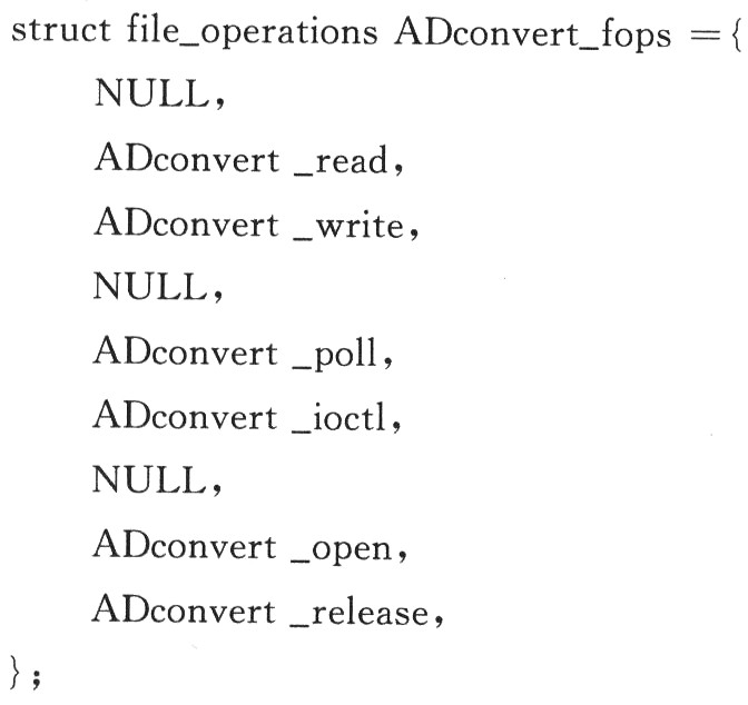
1 The application can access the hardware device only by operating the open, close, read/write, ioctl, etc. of the device file. The extended file operation structure file_operations of Linux implements the mapping of standard file operations to hardware device operations, and each device driver The program must implement some or all of the functions defined by this interface. The extended file operation structure of the A/D driver is as follows:
2 Using interrupts in device drivers is an effective means of increasing the system's data processing rate. There are two things to do:
First, after the register_chrdev() call in the initialization function, use the request_irq() function to install the interrupt handler. The request_irq() function is declared as follows:
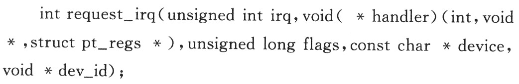
The parameter irq is the device interrupt number used by the driver; the handler is the interrupt service function pointer; the flags is a byte mask of various options related to interrupt management; the device is used in /proc/interrupts to display the interrupted possession ; dev_id This pointer is used for the shared interrupt signal line, returning 0 success, non-zero failure.
The A/D driver installs an interrupt handler as follows:
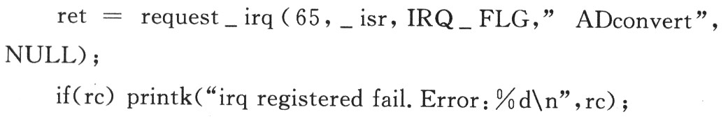
Second, to implement this interrupt service routine, the parameters must be consistent with the request_irq() registration requirements, and must not have a return value.
3A/D initialization

Conclusion Based on ARM core, LPC2292 is the embedded vehicle driving monitoring terminal with control core. It has added several new functions to the existing driving recorder. It has the following characteristics:
1 With μClinux system as the data processing platform, the multi-task process scheduling mechanism greatly improves the system's ability to process massive data, and the real-time performance is greatly improved. The parameters requiring high monitoring frequency such as vehicle speed, engine speed and brake pressure can be accurately monitored. , enhance the driving safety of the vehicle.
2 advanced communication functions. The CAN and LIN bus interfaces enable the terminal to be integrated with a vehicle with a universal bus interface. As a built-in diagnostic device for the vehicle, the terminal can acquire vehicle parameters in all directions. The USB interface allows monitoring data to be easily saved to the backend of the system for data analysis.
3 perfect data upload and vehicle location tracking function. The manager can not only know the current status of the vehicle in real time, but also monitor the running status of the vehicle in real time. Through the dual monitoring of the driver and the manager, the safe operation of the vehicle can be effectively ensured, which is of great significance for vehicles engaged in high-risk transportation industry.
In short, the application of high-performance ARM microcontroller and embedded operating system in the vehicle monitoring terminal can greatly improve the efficiency and accuracy of vehicle data acquisition and analysis, and realize real-time monitoring of various performance parameters of vehicles. It is the development trend of remote real-time monitoring technology for vehicles in the future.
Editor's Note: This article is an abbreviated version of the journal. The full text can be found on the website Com. Cn.
Melamine Board,ther Plywood,MDF with Melamine
Hand Tools Co., Ltd , http://www.nshandtools.com