Simplified patient monitor system design based on ECG AFE

It's not hard to notice that in higher-level systems and component architectures of patient monitoring equipment, many data acquisition systems follow a typical signal chain, which includes signal acquisition, conditioning, processing, and communication. However, when you dig deeper, you'll find that there are numerous design challenges that must be carefully addressed—such as maintaining signal integrity, managing common-mode rejection, and ensuring the safety of patients using electrical devices. These factors add complexity, especially when considering scenarios like defibrillation, where the system must remain unaffected by high-energy shocks. In addition, industry standards, practical constraints, and evolving requirements also influence the final system design. Figure 1 illustrates the typical signal chain used in a 12-lead ECG (electrocardiogram) monitoring device. The architecture is highly intricate, with various nuances and challenges involved in its implementation.

Simplify patient monitor design with ECG AFE

ECG Monitoring ECG measurement captures the heart’s electrical activity, and it's used in a variety of devices such as portable dynamic ECG monitors, clinical electrocardiographs, and high-channel cardiac mapping systems. These systems operate in diverse environments, each presenting unique design challenges. For instance, in hospitals, ECG systems are used in operating rooms, intensive care units, and electrophysiology labs. Each setting brings its own set of complexities, from electromagnetic interference to power supply stability. As healthcare moves toward remote patient monitoring, developers face new challenges that require innovative solutions and more robust designs. ECG Signal An ECG signal represents the heart's electrical activity over time, captured through skin electrodes and recorded externally. It is a non-invasive method used by electrocardiograph devices. The amplitude typically ranges from 0.25mV to 5mV and consists of waves like the P wave, QRS complex, and T wave. These waves correspond to different phases of the heart’s cycle: the P wave indicates atrial contraction, the QRS complex reflects ventricular depolarization, and the T wave shows ventricular repolarization. Deviations from the normal sinus rhythm can indicate potential health issues, helping doctors assess a patient's condition. Sampling the ECG signal reveals these key components, which provide valuable insights into the heart’s function. As medical research advances, cardiologists can now identify a wide range of anomalies based on the electrical properties of the heart. This continues to expand the scope of ECG analysis and its application in clinical settings. ECG Measurement In ECG measurements, electrodes act as potential sensors placed on the chest and limbs. Leads are formed by mathematical combinations of these electrodes. Although some may consider the 12-lead system outdated, it remains the most widely used in clinical practice. The 12-lead ECG includes three standard limb leads (I, II, III), three augmented limb leads (aVR, aVL, aVF), and six precordial leads (V1–V6). The precordial leads are considered independent vectors, calculated as the difference between the Wilson central terminal and the specific V electrode. The Wilson center itself is derived from the average of the right arm, left arm, and left leg electrodes. As shown in Figure 4, the Einthoven leads and the V leads both represent vector views of the heart’s electrical activity. The signals from leads I, II, and III are measured between the arms or between one arm and the left leg. The augmented leads (aVL, aVR, aVF) are derived from the same three electrodes but with different reference points. For example, aVL uses the left arm as the positive electrode and the combination of the right arm and left leg as the negative electrode. Meanwhile, the precordial leads use the Wilson center as the reference point.

Simplify patient monitor design with ECG AFE

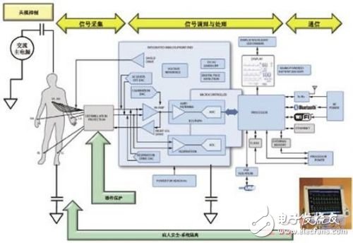
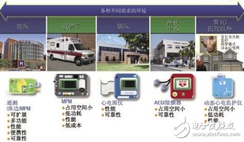
Figure 2: Environment that requires ECG monitoring in the healthcare system

Simplify patient monitor design with ECG AFE

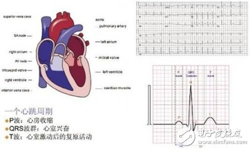
Figure 3: ECG signal

Simplify patient monitor design with ECG AFE

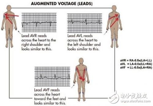
Figure 4: AVx lead measurement through the heart

Stage Speaker

Dsp Speaker,New Professional Speaker,Performance Speaker With Dsp,Active Speaker For Outdoor

NINGBO RFUN AUDIO TECHNOLOGY CO.,LTD , https://www.mosensound.com

Posted on