Recently, I have often asked friends about some problems in cable connection in the production of antennas. I would like to talk about some personal experiences here. In fact, I feel that the raising of these problems is mainly caused by the lack of long-term and short-term concepts.
First introduce the principle of the antenna:
An antenna is a transducer that transforms a guided wave propagating on a transmission line into an electromagnetic wave propagating in an unbounded medium (usually free space), or vice versa. A component used in a radio device to transmit or receive electromagnetic waves. Engineering systems such as radiocommunication, broadcasting, television, radar, navigation, electronic countermeasures, remote sensing, radio astronomy, etc., all use electromagnetic waves to transmit information, relying on antennas to work. In addition, non-signal energy radiation also requires an antenna in terms of transmitting energy using electromagnetic waves. Generally, the antennas are reversible, that is, the same antenna can be used as both a transmitting antenna and a receiving antenna. The same characteristic parameters of the same antenna as transmitting or receiving are the same. This is the reciprocity theorem of the antenna.
Then introduce two special transmission line segments: 1/4 wavelength transmission line and 1/2 wavelength transmission line, see the figure below.
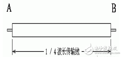
The figure shows a 1/4 wavelength transmission line. For example, our commonly used 75Ω and 50Ω RF coaxial cables can be used as a 1/4 wavelength transmission line at a certain frequency by selecting a certain length. This section of transmission line has a very important characteristic at the corresponding frequency point: when the A terminal is short-circuited, the impedance of the B terminal is infinite; when the B terminal is short-circuited, the impedance of the A terminal is infinite. Similarly, when one end is open, the other end is infinitely small.
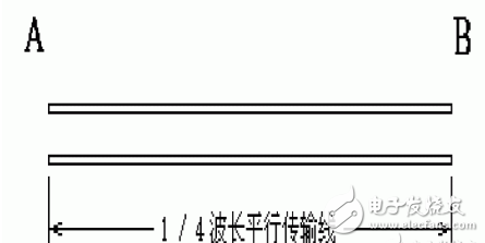
This feature also applies to parallel transmission lines as shown in the figure below, such as the 300Ω balanced transmission line commonly used in earlier years.
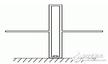
This characteristic of the 1/4 wavelength line can sometimes bring us great convenience, and the half-wave vibrator antenna as shown in the following figure takes advantage of this feature.
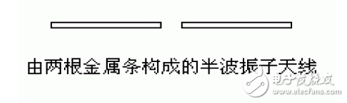
The upper left picture shows a commonly used half-wave vibrator antenna consisting of two metal strips or metal tubes. This kind of antenna does not have a zero potential point for common fixation, just like the folded vibrator antenna. Solve the problem well. The structure inside the dotted line can be regarded as the 1/4 wavelength transmission line short-circuited at the lower end, and the impedance at the upper end is infinite, which can be used as a fixed half-wave oscillator support structure.
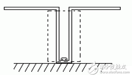
Therefore, the structure of the figure below is easy to understand.
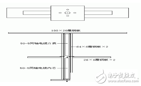
Looking at the 2.4GHz band feed in the figure below, this is the structure.
CCTV Baluns,Video Balun Transceiver Transmitter,Passive Video Balun,HD CCTV Video Balun
Chinasky Electronics Co., Ltd. , https://www.chinacctvproducts.com