With its powerful features, USB type-c will quickly trigger a revolution in USB interface under the strong promotion of Apple, Intel, Google and other vendors, and will positively affect all aspects of our daily lives. This article discusses an important professional question: Does the USB type-c device require CC logic detection and control chips?
To answer this question, we must start with the basic concepts.
DFP (Downstream Facing Port): The downlink port can be understood as Host, DFP provides VBUS, and can also provide data. A typical DFP device is a power adapter because it always provides power.
UFP (Upstream Facing Port): Upstream port, which can be understood as Device. UFP takes power from VBUS and can provide data. Typical devices are U disk, mobile hard disk, because they are always read data and take power from VBUS, of course, does not rule out the possibility of a U disk that can be used as a host in the future.
DRP (Dual Role Port): Dual role port. DRP can be used as DFP (Host) or UFP (Device). It can also be dynamically switched between DFP and UFP. A typical DRP device is a computer (the computer can be used as a USB host, or as a charged device (Apple's new MacBook), an OTG-enabled mobile phone (a mobile phone can be used as a device for charging and reading data, or as a device). The host provides power to other devices or reads data from the USB flash drive. The mobile power supply (discharge and charge can be discharged through a USB type-c, that is, the port can be discharged or charged).
CC (ConfiguraTIon Channel): Configure the channel, which is the key channel added in the USB type-c. It functions to detect the USB connection, detect the forward and reverse insertion, and establish and manage the connection between the USB device and the VBUS.
USB PD (USB Power Delivery): PD is a communication protocol, which is a new power and communication connection method, which allows transmission of up to 100W (20V/5A) power between USB devices, and it can change the port. The attribute also allows the port to switch between DFP and UFP, and it can also communicate with the cable to obtain the properties of the cable.
Electronically Marked Cable: USB Type-C active cable packaged with E-Marker chip. DFP and UFP can read the properties of the cable using PD protocol: power transmission capability, data transmission capability, ID and other information. All full-featured Type-C cables should be packaged with E-Marker, but USB 2.0 Type-C cables may not be packaged with E-Marker.
The USB Type-C device DFP-to-UFP configuration process and VBUS management have the following main processes:
Device connection and separate detection: When DFP needs to detect a certain voltage on the CC pin, it is judged that the UFP device has been inserted or removed to provide and manage VBUS. When no UFP device is inserted, VBUS must be turned off. There are the biggest differences in power adapters. Therefore all DFP devices require CC logic detection and control chips as well as VBUS switch circuits.
Insertion direction detection: As shown in Figure 1, although the USB Type-C socket and the two rows of pins of the plug are vertically symmetrical, the USB data signal has two sets of repeated channels, but the main control chip usually has only one set of TX/RX and D+/-. aisle. Since the data rate of USB2.0 is only 480Mbps, the data transmission quality can be better without considering the impedance continuity of the signal trace. Therefore, the D+/- signal of USB2.0 can be directly controlled from the main control chip without being controlled by the MUX. Connect one to two to the two sets of D+/- pins on the USB Type-C socket. However, the data rate of USB3.0 or USB3.1 is as high as 5Gbps or 10Gbps. If the signal line is still divided into two, the discontinuous signal line impedance will seriously damage the data transmission quality. Therefore, the MUX switch must be used to ensure the signal path. Impedance consistency to ensure signal transmission quality. The MUX shown on the right side of the figure below selects one of TX1/RX1 and TX2/RX2 to connect to the master chip, and this MUX must be controlled by CC Logic.
Therefore, in the USB2.0 application, there is no need to consider the direction detection problem, but in the USB3.0 or USB3.1 application, the direction detection problem must be considered.

Figure 1 USB Type-C data routing logic model
However, it must be noted that in the application of USB3.0/USB3.1, there is a case where the MUX is not needed, that is, no direction detection is required, as shown in Fig. 2, whether it is positive or negative, the left host can The MUX is switched according to the state on the CC pin to connect the USB3.0/USB3.1 signal. This scenario occurs when the device on the right is always UFP, such as a USB flash drive, a removable hard drive, and so on.
Therefore, in USB3.0/USB3.1 applications, all devices except UFP devices require CC logic detection and control chips.
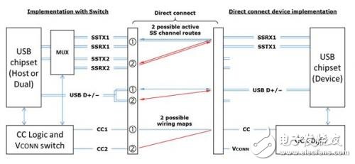
Figure 2 USB Type-C direct connection data routing logic model
DRP switches between DFP and UFP every 50ms in standby mode. When switching to DFP, there must be a resistor Rp pulled up to VBUS or a current source on the CC pin. When switching to UFP, there must be a resistor Rd pulled down to GND on the CC pin. This switching action must be This is done by the CC Logic chip.
When DFP detects UFP insertion, it can output VBUS. When UFP is pulled out, VBUS must be turned off. This action must be completed by CC Logic chip.
USB Type-C has added new current detection and usage functions. Three new current modes are added: default USB power mode (500mA/900mA), 1.5A, 3.0A. Three current modes are transmitted and detected by CC pin. For DFPs that require broadcast current output capability, it is necessary to use different values ​​of CC pull-up resistor Rp. For UFP, it is necessary to detect the voltage value on the CC pin to obtain the current output capability of the other DFP.
USB PD communicationUSB PD seems to be just a protocol for power transmission and management. In fact, it can change the port role, communicate with active cables, and allow DFP to become a high-level function such as powered devices. Therefore, devices supporting PD must use CC Logic chips.
Discover and configure extensions to other peripherals (Audio, Debug) The USB Type-C supports voice accessories and Debug mode. If the USB Type-C interface is only used as a UFP and does not need to detect the power supply capability of the DFP because of its low power consumption, the CC Logic chip is not required.
In summary, all DFPs (such as power adapters), all DRP (such as computers, mobile phones, tablets, mobile power), all UFPs that need to detect DFP current output capability, all PD-capable devices require CC logic detection and port Control chip. In other words, only the UFP (U disk, earphone, mouse, etc.) that does not need to detect the current capability because of low power consumption does not require the CC logic to detect the port control chip.
PC Cable:MINI DIN,D-SUB,SCSI.The display connecting line includes the data cable connecting the host computer and the display screen, and the power cable connecting the power supply.
The common data cable types are: HDMI cable, VGA cable and DVI cable. There is also a DP cable for notebook!
This product is suitable for computer and automatic connection cable with rated voltage of 500V and below. K type B low density polyethylene (LDPE) with oxidation resistance is used for insulation of cable ground wire core. Polyethylene has high insulation resistance, good voltage resistance, small dielectric coefficient and small influence of dielectric loss temperature and variable frequency. It can not only meet the requirements of transmission performance, but also ensure the service life of the cable. One
In order to reduce the mutual crosstalk and external interference between loops, the cable adopts shielding structure. According to different occasions, the shielding requirements of cables are as follows: the combined shielding of twisted pair, the total shielding of cable composed of twisted pair, and the total shielding after the combined shielding of twisted pair.
Shielding materials include round copper wire, copper strip and aluminum / plastic composite belt. Shielding pair and shielding pair have good insulation performance. If there is potential difference between shielding pair and shielding pair, the transmission quality of signal will not be affected.
PC Cable
ShenZhen Antenk Electronics Co,Ltd , https://www.antenksocket.com