Abstract: An automotive electronically controlled air suspension system based on Freescale MC9S08GB60 microcontroller is designed. The hardware circuit system and specific circuit design are emphasized, and the software design points are introduced. Through the bench test in the laboratory, it is verified that the system effectively improves the suspension travel, wheel dynamic load and vertical acceleration of the vehicle with respect to the passive suspension system, and improves the height adjustment control of the vehicle. The comfort of the car. And the circuit structure is simple, the stability is good, and the value of practical application.
Keywords: MC9S08GB60 electronic control unit air suspension
Design of the Vehicle's Electronically controlled air suspension system Based on Freescale HCS08 QuanLi 1 XiePing1 BaiLu2 (1.Jiang Su University, Institute of Electric Engineering, JIANG SU ZHEN JIANG 212013
2. HEBI technical school HENAN HEBI 458000)
Abstract:The Vehicle's electronically controlled air suspension system were designed, which
Use a microcontroller Freescale MC9S08GB60.Emphasizes the circuit of the hardware system,meanwhile, introduces the key point on the software design. The bench test in laboratory certified that the ECAS relative passivity-suspension , it improved three impotent index arm effectively,which are suspension's Moving distance, acceleration in vertical and the cartwheel moving loading.it improve the vehicle's ride comfortable when controlling the ride height. The system is simple structure , stability and practical.
Keywords:MC9S08GB60 ECU Air Suspension
0 Introduction Air suspensions mainly have passive suspensions and controllable electronic suspensions. The passive suspension suppresses and reduces the dynamic load and vibration of the car body and the wheel to a certain extent, ensuring the driving safety and the ride comfort of the vehicle. However, since the stiffness and damping coefficient of the passive suspension are generally selected empirically, it is optimal only in certain environments, and once the load, road condition, speed and other factors change, the passive suspension cannot be automatically adjusted accordingly, and it cannot be adjusted manually. . To overcome this drawback, the Electronic Air Suspension System (ECAS)
This is produced. ECAS is currently the most advanced car suspension system. It can automatically adjust the suspension stiffness, body height, air consumption, and has the advantages of quick response, easy installation and simple operation, along with changes in road conditions, load and speed. Therefore, the controllable electronic suspension has become a hot topic in the field of automotive electronics, and it has broad prospects for development.
1 Composition and principle of ECAS The electronically controlled air suspension system consists of an electronic control unit (ECU), a height sensor, an air spring, a speed sensor, a shock absorber, and a vehicle height lifting control keyboard. The ECU detects the height of the vehicle body in real time through the height sensor, indirectly obtains the vertical acceleration of the vehicle body, and detects the speed of the vehicle through the speed sensor. The ECU maintains several indicator heights and three levels of adjustable damping values, which are consistent with spring comfort, driving safety and application specifications. The vehicle speed is automatically executed by the ECU under different driving conditions, and the height and damping value can be manually controlled by the driver. By comparing the height sensor detection result with the indicator height, if the height difference exceeds a certain tolerance range, the solenoid valve will be excited, and the actual height will be adjusted to the indicator height by charging and discharging gas. The damper damping force is a total of three gears. The damper is controlled according to the vehicle's ascending speed and acceleration, and the corresponding damping force is executed to meet the requirements of the ride comfort and the ride comfort. The structure of the electronically controlled air suspension is shown in Figure 1.
This article refers to the address: http://

Fig 1 Electronically controlled air suspension structure
2 Design of each functional module of ECAS system
ECAS is mainly composed of six major functional modules, namely the central processing unit and the signal input module (ie sensor signal).
Signal output module (ie control output), operator interface module, power module, other modules (external memory, RS485
Communication, system upgrade port).
2.1 MC9S08GB60
The microcontroller is a core component of the ECU. It handles a large number of input and output signals frequently, and it requires high precision and real-time control. This design uses the enhanced 8-bit automotive microcontroller from Freescale, Inc. - MC9S08GB60
Single chip microcomputer. The device has 64K flash and 4K E2PROM, and is highly integrated with four serial communication ports.
(SCI1, SCI2, SPI, I2C), up to 8 timers (PWM), 8-channel 10-bit A/D converter module.
2.2 Signal Sensing Input Module This module is mainly composed of 3 height sensors and 1 speed sensor. The body height sensor is equivalent to the series resistance of the inductor. The equivalent inductance corresponds to about 20mH at 0° corner, about 8mH at -45° rotation angle, and about 35mH at +45° rotation angle.
The equivalent resistance is 120Ω. To this end, an LC three-point oscillating circuit is designed to detect the signal from the vehicle height sensor. A sine wave generator is designed, which is composed of TL082 components and peripheral circuits. The frequency of the sine wave changes continuously with the change of the equivalent inductance of the height sensor. Then, a square wave whose frequency changes with the inductance is outputted by the comparator, and is input to the input capture port of the MCU through triode amplification and optocoupler isolation. The MCU detects the transmitted signal from the height sensor by detecting this changing frequency. The circuit is shown in Figure 2. The detection of the speed sensor signal is also achieved by detecting the frequency.
The principle is similar to the height sensing input circuit.
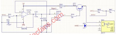
Figure 2 body height detection circuit
Fig 2 detection circuit of vehicle's height
2.3 signal control output module
The ECU uses the PWM mode output to control the opening of the solenoid valve, and outputs a control signal according to the deviation between the current actual height and the expected adjustment height. The ECU calculates the adjustment pulse length of the solenoid valve. If the amount of height to be adjusted is large, the ECU will give a long pulse because there is no danger of overshoot. At the same time, the fast rising speed will reduce the pulse length, so that the vehicle can be accurately controlled. The height adjustment speed greatly avoids the high overshoot and oscillation adjustment. For the solenoid valve drive, the design uses the NUD3124 relay driver chip produced by ON Semiconductor. The high reverse avalanche energy capacity (350mJ) of the NUD3124 (car version) device controls most relays used in automotive applications. The control signal is isolated by the optocoupler and output to the NUD3124 driver chip. The NUD3124 drives the solenoid valve and adds a diode protection circuit to the output of the NUD3124.
2.4 Power Module, Operator Interface Module and Other Extended Function Modules
The ECAS system has two main voltage sources, one is a 24V voltage source and the other is a 3V voltage source. The 3V voltage source is divided into a digital voltage source and an analog voltage source. The 24V power supply is taken out by the vehicle's own power supply, then filtered by the π-type filter, and then stabilized by the Zener diode. After passing through a filter circuit, a stable 24V voltage source is finally obtained. The 3V voltage source is similar, except that an isolation resistor is required between the digital power supply and the analog power supply to prevent crosstalk.
The operation interface is mainly keyboard input and LED display. When the driver wants to manually control the damping and vehicle height, he can input its operation through the keyboard, and then the corresponding LED lights up to display its input. The keyboard input is filtered, optocoupler is isolated and IC106 filtered and protected, and finally sent to the ECU, and then the ECU output control drives the corresponding LED to illuminate.
Other modules mainly include interfaces for future upgrades, as well as RS485 communication, large-capacity memory, and so on. The mass storage uses ATMAL's AT24C1024, which is connected to the microcontroller via PTC2/SDA and PTC3/SCL; RS485
With the typical connection method, the chip adopts max3485; other unused pins are led out through the slot for future upgrade.
3 Automotive ECAS software design program Air Suspension Electronic Control Unit (ECAS) application software is determined by the system initialization module, manual automatic height adjustment module,
A signal acquisition module, a keyboard response module, an output control module, and the like. The main program is a loop body, which is responsible for adjusting the height and damping of the vehicle body. The vehicle height signal is converted into a square wave signal with a certain duty ratio by the sensor, and then compared with the preset calibration height in the microprocessor, and the output is output. The control signal, when reaching the calibration height, reduces the duty cycle of the output signal to prevent overcharging. The specific main block diagram is shown in Figure 3.

Fig 3 the structured flowchart of main program
4 Test and result analysis This design has made a two-degree-of-freedom 1/4 vehicle air suspension test. By comparing the analysis of the electronically controlled air suspension and the passive air suspension under the same road excitation under different frequency characteristics, different results are obtained. Suspension travel, vehicle dynamic load and vertical acceleration to verify the feasibility of the design [4], to verify whether the design has achieved the purpose of improving vehicle ride comfort and ride comfort. Provide technical reserves and test methods for the next step of converting scientific research results into automotive electronic products.
This test system uses the US INSTRON 8800 CNC hydraulic servo vibration test system, air spring, shock absorber, controller designed in this paper, acceleration sensor, body height sensor, speed sensor, Wavebook signal collector, computer and so on. The test principle is shown in Figure 4. Two additional sensors are added to the test system, namely the acceleration sensor and the pressure sensor. These two sensors are added to measure the sprung vertical acceleration and the tire dynamic load. During the test, the excitation signal is a random input signal of white noise with simulated B-class road surface and vehicle speed of 50km/h. The test time is 30s, the sampling interval is 0.01s, and the air spring working height is 275mm. The air suspension is added before and after the controller. On-spring mass vertical vibration acceleration, suspension travel and tire dynamic load. The experimental results are shown in Figure 5. Through this experiment, we can see that the electronically controlled air suspension system designed by this paper is obviously more obvious than the passive suspension in the suspension travel, vehicle dynamic load and vertical acceleration. The improvement, the root mean square value of the sprung mass vertical vibration acceleration decreased by 12.89%. The controller designed in this paper effectively improves the ride comfort of the wheel, and obtains better suspension characteristics, which has practical application value. !

Figure 5 (b) Vertical acceleration diagram 5 (c) Wheel dynamic load
RAM/RFM Induction Heating Capacitors
RAM/RFM induction heating capacitors
RAM/RFM induction heating capacitors
YANGZHOU POSITIONING TECH CO., LTD , http://www.yzpstcc.com