1 Introduction
This article refers to the address: http://
When an engine powered by an ignition engine is running on the road, the high-pressure ignition system of the gasoline engine generates strong electromagnetic waves, interferes with the normal operation of the radio broadcasting and radio communication services around it, and pollutes the electromagnetic environment. Since then, people have listed electromagnetic pollution as one of the three major sources of pollution (emissions, noise, electromagnetic). The International Radio Organization began to study the sources of interference in this form of high-energy pulses and proposed measurement methods and limitations. At present, the control requirements for electromagnetic pollution have been included in the technical regulations of countries around the world. After years of technical specifications, the cars running on the market have basically achieved effective control of the ignition pulse electromagnetic noise. However, with the continuous advancement and development of automotive technology, the large number of applications of automotive electronic and electrical equipment, the characteristics of automotive electromagnetic interference and its impact have also undergone tremendous changes. The source of electromagnetic interference generated by automobiles is not simply an ignition system. A variety of electronic and electrical equipment used in vehicles also generate electromagnetic interference.
2. Electromagnetic interference analysis
2.1 interference source
The analysis of the interference source is the premise of protection. In the equipped vehicle, the electromagnetic environment is very complicated, mainly including radio equipment interference, pulse digital circuit and switching circuit interference, equipment cable interference and external interference. For equipped vehicles, due to the large number and variety of electronic equipment and instruments, wide frequency range, complex signal form, and large difference in signal strength, the harmonics generated by these signals and various intermodulation and intermodulation frequencies can pass. The antenna radiates electromagnetic interference around: in the electronic instrument and control system, electromagnetic interference occurs due to sudden changes in voltage and power supply, component mounting position, wiring impedance, oscillation circuit interconnection, component or circuit coupling; The installation space of the microcomputer system is small, the wiring is complicated, and the wirings of various cables such as power lines, signal lines, and control lines are very dense, and the signal strengths of the various cables are largely different, and the sensitivity is different, which easily causes mutual interference. External electromagnetic noise refers to electromagnetic noise radiated by nature and various external electrical equipment, such as lightning, radio radar, navigation system, broadcast television system, transient switch, reversing device, gas spark arrester, corona discharge, contact potential , sine wave signal source, non-sinusoidal signal source, electromagnetic pulse, etc.
There are many large-scale integrated circuit chips inside the microcomputer equipment, including TTL high-speed digital logic components and CMOS high-functionalized components. Each component and each wire has different currents, which generate large and small electromagnetic fields around it. Since the computer operates at frequencies from a few megahertz to hundreds of megahertz, radiation and coupling cause mutual interference. When the equipment is in high-speed operation, they are not only the radiation source of electromagnetic interference, but also the object of interference.
2.2 Interference formation and transmission
If the wavelength of the interfering signal is smaller than the structure size of the interfered object, or the distance between the interferer and the victim is > wavelength/2II, the interfering signal can be considered as the radiated field, which radiates the electromagnetic field energy in the form of a plane electromagnetic wave. Enter the path of the interfered object. The interfering signal is in the form of leakage and coupling, through the insulating support as a medium, coupled to the interfered line, device or system via common impedance coupling. When the wavelength of the interference signal is longer than the structural size of the interfered object, or the distance between the interference source and the interference object is > wavelength/2II, the interference signal can be regarded as a stable field, and it enters the path of the interfered object in the form of an inductive field. . Interference signals can be introduced into a line, device, or system by direct conduction.
As far as the on-board microcomputer system is concerned, the interference between the power line and the signal line, the strong signal line and the weak signal line is mainly transmitted by the electric field coupling; the electromagnetic interference generated by the power converter, the driving motor of the Weitong antenna and the like is mainly Propagation in the form of low-frequency magnetic field coupling; if the system is not well grounded, or the grounding resistance is too large, the circuits of different circuits will form mutual interference through the common grounding resistance. The electromagnetic signals transmitted by wireless devices such as Weitong, ultrashort wave, and telemetry are connected to the antenna through the antenna in the electromagnetic coupling of the antenna. The frequency source, inverter, mixer, etc. pass the shield, the button and the gap of the display head to electromagnetic The form of radiation on the signal line is field-to-line coupling, and the high-frequency signal sense between the two parallel wires is line-to-line coupling.
In order to solve the electromagnetic interference problem in the application and promotion of microcomputer equipment in equipment vehicles, according to the above analysis, we mainly take the following measures to protect against electromagnetic interference.
3.1 power supply filter
Filtering is an important concept in signal processing. Filtering is divided into classical filtering and modern filtering. The concept of classical filtering is an engineering concept based on Fourier analysis and transformation. According to the theory of higher mathematics, any signal that satisfies certain conditions can be regarded as being superimposed by an infinite number of sine waves. In other words, the engineering signal is a linear superposition of sine waves of different frequencies. The sine waves of different frequencies that make up the signal are called the frequency components or harmonic components of the signal. A circuit that allows only signal components in a certain frequency range to pass normally, while blocking another part of the frequency component, is called a classical filter or a filter circuit.
Small-scale, high-efficiency switching power supplies are used in microcomputer equipment systems, and the rectification harmonics, switching frequency and harmonics of the switching power supply, and the high-speed current and voltage transients inherent in switching are severely affected by electronic systems. Interference, the interference frequency is between 30kHz and 30MHz. Therefore, the power supply filter must be added at the input and output of the power conversion, and the input and output leads of the filter are also required to be isolated to prevent the filter from interfering with the signal through the radiation coupling. The ability to suppress. The purpose of adding the power supply filter at the input end is mainly to suppress the interference of the high-frequency interference signal input from the AC terminal of the power supply to the system. The purpose of the output power supply filter is mainly to prevent the electromagnetic interference generated by the system from being transmitted to the other through the common power supply channel. In the electronic system. The digital signal line filter is used to eliminate high frequency electromagnetic interference in the signal line. The main method is to use a high frequency absorption capacitor or an EMI absorption ring. Specifically, a high-frequency absorption capacitor is connected to the input end of the digital signal line for absorbing electromagnetic interference introduced from the digital signal input end, and an EMI absorption magnetic ring may be placed on the shielding layer of the digital signal line.
A good filter circuit, placed in the front stage, eliminates most of the interference noise that enters the system due to conduction at the entrance to the circuit system. The interference that the power filter needs to eliminate is differential mode interference and common mode interference. The differential mode interference is caused by harmonics generated in the automotive electronic system and various spikes du/dt and dildt, while the common mode interference is the space electromagnetic wave. Caused by radiation on the frame, because the negative pole of the power supply is connected to the frame, and the frame is insulated from the ground, the power supply system is a floating system, and the ground wire is susceptible to common mode interference.
The entire system uses a discrete power supply. It is not unified transformer rectification and filtering, and is used for each part. Instead, it is directly sent to each part for rectification, filtering and voltage regulation after being transformed. This reduces the risk of centralized power supply, improves the quality of the power supply, and increases the heat dissipation. area. In addition, the host and peripherals are divided into one type of power supply mode; air conditioning, lighting, etc. are divided into another type of power supply mode to avoid auxiliary equipment work. Interference with signal equipment through power supply.
3.2 hardware watchdog circuit to prevent interference.
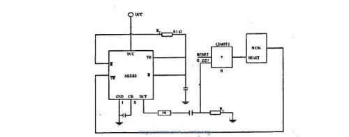
The monostable trigger NE555 is used as the microcomputer watchdog circuit; when the system works normally, the watchdog circuit does not work. When the system is not operating normally, the P1.1 pin of the 80C51 cannot send the trigger pulse to the timer. At this time, the single-state trigger of NE555 outputs a pulse width greater than 4US negative pulse, which is added to the reset end of 80C51 after F6 inversion, so that the system can be reliably reset, so as to prevent the program from running due to external interference, so that The microcomputer program runs normally, as shown in Figure 1.
3.3 Software Protection
The software anti-jamming of microcomputer equipment is mainly to stabilize the memory data and guarantee the program pointer. The microcomputer is a programmable control device, and the software can support and enhance the anti-interference ability of the hardware. The random memory RAM in the microcomputer system is mainly used for temporary storage of data, and the space is small. For the stored data, if the collected data is averaged as the sampling result, it can be avoided due to interference during the acquisition. The authenticity of the data; if the data stored in the random memory is lost due to interference or the data changes, the check flag can be set in the random memory area; in order to reduce the damage of the random memory area, the write signal line of the random memory chip can be The trigger device is added, and only when the CPU writes data, when the interference enters the microcomputer system and the program runs out of control, the runaway program may fall at any address in the ROM area of ​​the working program. The method is to make the program on the right track. The principle is to use the specific data encoding to verify the measurement data information during the storage, transformation, processing and transmission of data, so as to find the errors. During the execution of the program, once the error is found, the corrupted current instruction is re-executed. In addition, the program counter has to be returned one step in order to execute the instruction again. If the fault is transient, the error may no longer occur during repeated execution of the instruction and the program continues to run forward.
When the running out of control program falls into the ROM area of ​​the non-working program, the software trap should be used to put the program on the right track. Add some trap statements and trap exit statements in the appropriate places of the program, these statements do not affect the normal operation of the program. When the computer or single chip computer is subjected to strong electromagnetic interference, the program may be deadlocked. Once the program runs into the preset trap, the trap exit is preset by the designer, so the program enters the controllable phase. If the trap exit is the entry of the system program self-recovery, the system program can be restarted. Automatically resumes normal operation.
When the program is out of control, the out-of-control program often performs illegal write operations, which makes useful information lost. How to recover important information about the system. Re-entering normal working conditions is a very important issue. The reset operation caused by anti-interference measures should adopt "hot start". In order to make the hot start smooth, firstly, the interrupt should be turned off, all I/O devices should be set to a safe state, and I/O operations should be blocked to avoid more serious consequences. Then resume the information and re-enter the status. In order to ensure that the system can re-enter the normal operation state without disturbance, it is necessary to ensure the correctness of important data, that is, to prevent the illegal write operation of the RAM by the runaway program. At this time, it is necessary to add a lock signal to the RAM to realize the lock protection, thereby ensuring the data. Reliability of recovery.
4 Conclusion
The on-board microcomputer system developed by the above measures can work normally in the extremely harsh electromagnetic environment of the equipped vehicle. In short, the electromagnetic interference in the car and its impact are significant, related to the safety and reliability of the car. One should be aware that many of the new problems that arise in modern electronic vehicles are related to the effects of electromagnetic interference to a considerable extent. In practice, taking appropriate interference suppression measures and improving the electromagnetic immunity characteristics of automotive electronic and electrical components can effectively improve the operational reliability of automobiles.
New high mast light are driverless designed. The LED high mast lights are utilizing PHILIPS LUXEON 3030 2D luminous source, providing excellent lumen output – up to 150 LPW, long-lasting stability and splendid sight. Easy assemble/disassemble, neat wiring & connection, up to 115 LPW luminous efficiency, IP66 and IK10 Rated, 90%+ driver efficiency, over than 75,000 hours operation life and 5 years warranty. They are high intensity, durable lights that are typically used to illuminate large areas, flag poles, building facades, and many other applications.
High Mast Lighting,Stadium High Mast Lighting,Football Field High Mast Light,Aluminum Die Casting High Mast Lighting
Shenzhen Ri Yue Guang Hua Technology Co., Ltd. , https://www.ledlightinside.com