With the development of society, there are more and more families and public cars, and the number of stolen vehicles is increasing year by year. The traditional car alarm has many drawbacks, such as short acting distance, noise pollution, remote alarm, and installation. These drawbacks have brought great inconvenience to residents' lives. Some residential areas even prohibit the installation of car burglar alarms.
This article refers to the address: http://
The GSM (Global System for Mobile Communication) network technology is mature and covers a wide range of communication network systems that have been widely used. In recent years, basic service technologies such as SMS and call in GSM networks have also received more and more attention from circuit design engineers [1]. By combining the design idea of ​​the current car alarm and the functions of the GSM network, the remote alarm function of the anti-theft device can be realized, and the drawbacks of the conventional anti-theft device can be solved.
1 Overall design of anti-theft system and anti-theft device
1.1 Anti-theft system structure
The anti-theft system consists of a remote control, an anti-theft device, a GSM network, and a user's mobile phone. Its system structure is shown in Figure 1.
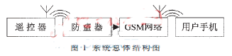
The anti-theft device can be placed anywhere in the car, and the state of the anti-theft device is controlled by a dedicated remote control. In the open state, when the sensor detects an abnormal signal, the anti-theft device can make a call to the user through the GSM network to achieve the purpose of remote anti-theft.
1.2 Anti-theft device internal structure design
The anti-theft device is composed of 5 modules: main control module, GSM module, detection module, remote control module and power module. The structure of the anti-theft device is shown in Figure 2.
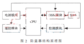
The main control module is responsible for receiving and processing signals sent by the remote control module, the GSM module and the detection module, and sending control commands to the GSM module.
The remote control module is used to control the working state of the entire system. When the remote control has a button press, the corresponding pin of the receiving module will output a signal, and the signal is sent to the CPU through the external interrupt interface of the single chip microcomputer, and the CPU enters the interrupt program to perform the opening and closing operations after receiving the signal.
The GSM module is responsible for sending a call signal to the user's mobile phone in accordance with the instructions of the CPU for alarm.
The detection module is responsible for detecting abnormal vibration signals of the car.
The power module is responsible for powering the entire anti-theft device, and it is necessary to solve the problem of the working time of the power module.
2 hardware circuit design
According to the function and design requirements of each module, the main components of each module of the system were selected and the specific circuit was designed.
2.1 main control module
The system requirements for the CPU are: 2 interrupts that support power-down wake-up; a pair of serial ports to communicate with the GSM module; 4 I/O ports to control the sound and light and GSM module enable; a certain amount of EEPROM space to store users Information such as phone number and an I/O port with A/D conversion to measure the completion status of battery charging.
In order to achieve the above requirements while minimizing the size of the anti-theft device, the design of the SOP-type chip STC12LE5402AD of Hongjing Technology was selected as the CPU of the anti-theft device. It has only 20 pins, operating voltage is 2.2 V to 3.8 V, operating frequency is 0 to 35 MHz, 1 KB EEPROM, 2 external interrupts that support power-down wake-up, a pair of serial ports, 15 I/O ports, 8-channel 10-bit A/D conversion I/O port with built-in reset circuit and low power consumption, fully in line with design requirements. The circuit of the system main control module is shown in Figure 3.
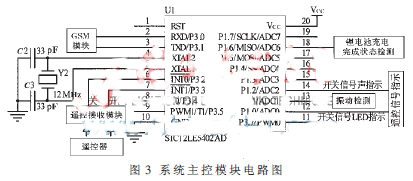
The remote control receiving module detects the turn-on signal of the remote controller, and transmits the signal to the CPU through the external interrupt port, and the anti-theft device enters a working state. When the vibration detecting module detects the abnormal vibration signal, the CPU turns on the SIM900B through the I/O port, and sends an AT command to the GSM module to initialize the SIM900B module. The GSM module sends a call alert signal to the user over the GSM network.
When the remote control receiver module detects the remote control's shutdown signal, the CPU will enter the low power mode through specific commands. When the remote controller sends a switch signal, the remote control signal indicating circuit will give an audible and visual indication.
2.2 Introduction to GSM Module
The GSM module uses SIMCOM's SIM900B module. The module is small in size and stable in performance. It has its own antenna buckle and is cost-effective. It has four working frequencies: GSM/GPRS 850/900/1800/1900 MHz, which can realize voice and SMS. , low-power transmission of data and fax information [2], to meet the system requirements for the GSM module.
The schematic diagram of the circuit connection of SIM900B is shown in Figure 4. U3 is a SIM card, and the SIM900B provides power to the SIM card through its own SIM card interface and sends commands to it to implement functions such as SMS and call. D4 to D7 are transient voltage suppression diodes placed near the SIM card holder to prevent electrostatic damage.
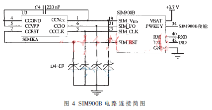
The PWKEY pin is the enable end of the SIM900B. After the software pulls the pin low for at least 100 ms, the SIM900B enters the enable state. At this time, the CPU can send commands to the SIM900B through the serial port.
2.3 detection module
Considering that most of the cars are stolen, abnormal vibrations occur, and the vibration sensor is designed as a signal detecting device. The vibration sensor is also called a vibration switch, and it generally has two types of ball type and spring type. The ball-type vibration switch has tilt sensing and can only be triggered in one direction; the spring-plate type vibration switch has no directional limitation and can be triggered at any angle [3]. In response to the above problems, the spring-type vibration switch SW-58010S was selected as the vibration detecting device.
The spring-plate type vibration switch is in an open-circuit OFF state when it is at rest. When it is touched by an external force to reach the corresponding vibration force, or the moving speed reaches an appropriate distance (bias), the conductive pin will be turned on instantaneously in an instant ON state; When it disappears, the switch returns to the open circuit OFF state. In the circuit, the vibration switch is grounded at one end, and the other end is connected to the I/O port of the single-chip microcomputer. When the vibration switch is subjected to external force vibration, the I/O port receives a low-level signal, and the system judges the signal and executes the corresponding program [4] .
2.4 remote control module
The system adopts XD-YK04 wireless transceiver module to realize the switch control of the anti-theft device. The remote control is coded with the SC2260 chip fixed code, and the remote control distance is 30 m to 50 m. The remote control receiver module operates from 3 V to 5 V, and the decoder chip uses the SC2272-M4. When the remote control button is pressed, the remote control receiving module transmits the signal to the CPU through the external medium port. Since the CPU interrupt uses the falling edge trigger and the remote control module outputs a high level signal, the output signal of the remote control receiving module must be inverted.
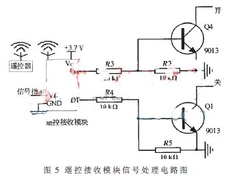
The signal processing circuit diagram of the remote control receiving module is shown in Figure 5. When the remote control "on" button is pressed, the D0 port outputs a high level, the transistor Q4 is turned on, the module output end is changed from the original high level to the low level, the CPU external interrupt is triggered and the interrupt program is executed, the system is Wake up to work. Similarly, when the "off" button is pressed, the anti-theft device will enter a power-down state.
2.5 power module
Considering that the anti-theft device is small in size, long in standby time, and internal components can work normally below 3.7 V, the design uses a mobile phone lithium battery as the system power supply. The battery capacity of the mobile phone is larger than that of the general button battery, the volume is relatively small, and the power supply time is long. Therefore, when the battery capacity is 1 500 mA/h, it can be used for about 20 days on a single charge.
The operating voltage of the CPU in the anti-theft device is 2.2 V to 3.8 V, and the operating voltage of other modules is about 3.7 V. Therefore, the lithium battery can supply power to the CPU and its peripheral circuits after being stepped down.
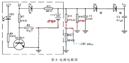
The external charger provides 5 V to charge the battery in the immobilizer and power each module. The specific power supply circuit is shown in Figure 6. In the figure, the 3.7 V battery is a lithium battery. As shown in the circuit inside the dotted line, when there is an external 5 V power supply, the battery is divided by R13 and R16 to obtain a voltage of 4.3 V. This voltage is used to charge the lithium battery with a cutoff voltage of 4.2 V. At this time, Q2 is turned on, and LED1 is red. A light to indicate that the system is charging. The potentiometer consisting of R14 and R15 can detect the completion status of the battery. When the battery is full, the CPU control power charging indicator turns green. When there is no external power supply, the lithium battery is used for the anti-theft device. At this time, Q2 is not conducting, and the LED1 is off.
Under working conditions, the output voltage of the lithium battery is 3.7 V. Diodes D2 and D3 are germanium diodes. The voltage drop during operation is 0.2 V to 0.3 V. After 4.7 V is stepped down, a voltage of 3.1 V to 3.3 V is obtained. This voltage supplies power to the CPU.
3 software design
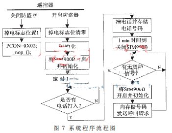
The system has two states: on and off. The system program flow is shown in Figure 7. When the system is in the "on" working state, press the "off" button, and the system executes the interrupt program of the "off" button. After the register PCON is set to 0x02 in the program, the system will enter the power-down mode. In this mode, the CPU external clock is stopped, the CPU, timer, and serial port all stop working, but the external interrupt still works normally, and the CPU can be woken up from the power-down mode, thus saving the power consumption of the anti-theft device.
When the system is in power-down mode, the system is “awakened†by the remote control and the system is woken up to the working state by an external interrupt. After the system wakes up from the power-down mode, it first executes the instruction after the power-down command before entering the interrupt service routine. Therefore, when writing a program, a nop instruction is usually added after the instruction that causes the system to enter the power-down mode, for example:
PCON=0X02;
_nop_();
The anti-theft storage unit can store a phone number. The user dials the anti-theft device number once with the mobile phone, and the user's mobile phone number will overwrite the number stored before the anti-theft device. In the working state, after an abnormal vibration signal appears around the anti-theft device, the CPU will control the GSM module, and use the SIM card to automatically dial the number stored in the system through the GSM network to prompt the user, and the user can hang up after being informed.
In this paper, STC12LE5402AD is the main control chip, SIM900B is used as the GSM module, and a small car alarm is designed with the vibration sensor as the signal detector. The anti-theft device can realize the functions: when the vehicle is illegally started or moved, the owner can be notified in time to effectively prevent theft of the vehicle; after the vehicle is stolen, the public security department can monitor the stolen vehicle in real time through the GSM network as long as the vehicle is activated. s position. The anti-theft device is small in size, requires no installation, no noise pollution and low cost, and is easy to promote.
Agriculture Drone Include the Agricultural Spraying Drones , Agricultural Crop Analysis Drone, Mist Sprayer Drone, Fertilizer Spreading Drone ,Tichogramma Dropper Drone etc. Use the Agricultural Drone can stop crop diseases with higher efficiency than the traditional method. For a farmer,Agriculture Drones is a tool,The Most important is they need a reliable drone can work continuouse, And lower cost of the spare parts, Easily maintenance, Thoese is what we did.
A stronger frame with light weight like a foundation of a building. We use carbon fiber and Aluminium Alloy made our Drone Frame , from the farmers spraying work experiences to improve the stable structures. And improve the Drone Motors and Drone Propellers to get more thurst and lower current for longer flight time.


Agriculture Drone
Drone Farming,Crop Spraying Drone,Agriculture Drone Spraying,Use Of Drones In Agriculture
shenzhen GC Electronics Co.,Ltd. , https://www.jmrdrone.com