First, the circuit analysis of anti-surge
Figure 1 shows the pre-EMC schematic diagram commonly used in low-power power modules. FUSE is a fuse, MOV is a varistor, Cx is an X capacitor, LDM is a differential mode inductor, Lcm is a common mode inductor, and Cy1 and Cy2 are Y capacitor, NTC is the thermistor. The main role of Y capacitors, common mode inductors, etc., is not to improve the surge immunity of the circuit, but they indirectly affect the design of the anti-surge circuit.
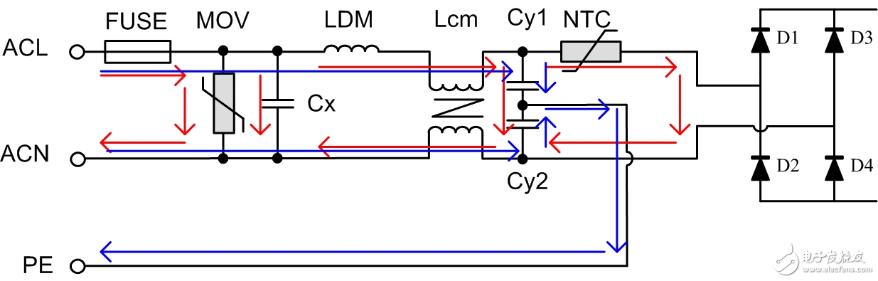
Figure 1 Common EMC pre-stage circuit
The surge voltage applied between the ACL and the ACN is called the differential mode surge voltage, and the differential mode path is shown by the red line in the figure; the voltage applied between the ACL (or ACN) and the PE is called the common mode surge voltage. The common mode path is shown by the blue line in the figure.
Before designing the anti-surge circuit, the corresponding "electromagnetic compatibility standard" must be determined. For example, the surge immunity requirement, test method, test level, etc. specified in IEC/EN 61000-4-5 (corresponding to GB/T 17626.5) . Below we will discuss the design of anti-surge circuits based on the provisions of this standard.
The surge generating circuit generates a surge voltage of 1.2/50 μs when the output is open, and generates a surge current of 8/20 μs when shorted.
The effective output impedance of the generator is 2Ω, so when the peak value of the open circuit voltage is XKV, the short-circuit peak current is (X/2)KA.
When the anti-surge test is performed between ACL (or ACN) and PE, a 10Ω resistor is serially connected to the coupling circuit, ignoring the influence of the series coupling capacitor, the short-circuit peak current becomes about (X/12). KA.
Second, related device introduction
Varistor
The most important parameters for varistor selection are: maximum allowable voltage, maximum clamping voltage, and withstand surge current.
First, ensure that the maximum allowable voltage of the varistor is greater than the maximum value of the output voltage of the power supply; secondly, ensure that the maximum clamp voltage does not exceed the maximum surge voltage allowed by the latter circuit; finally, the surge current flowing through the varistor should be guaranteed. It will not exceed the surge current it can withstand.
Other parameters such as rated power, maximum energy pulse that can withstand, etc. can be determined by simple verification or experiment.
2.Y capacitor
When performing common mode surge test, if the varistor or other device for clamping voltage is not added to the common mode path, the Y capacitor withstand voltage is higher than the test voltage.
3. Input rectifier diode
Assuming that the surge voltage is clamped by the varistor, the maximum clamp voltage is greater than the maximum reverse voltage that the input rectifier diode can withstand, and the diode may be damaged. Therefore, a diode with a reverse withstand voltage greater than the maximum clamp voltage of the varistor should be selected as the input rectifier diode.
4. Common mode inductance
In theory, the common mode inductor only works in the common mode path, but because the two windings of the common mode inductor are not fully coupled, the uncoupled portion will act as a differential mode inductor in the differential mode path, affecting the EMC characteristics.
Third, the case analysis
Background: Take a power module of a certain model as an example. This module is a power module customized by Zhou Ligong Zhiyuan Electronics for a customer. It inputs 85VAC~350VAC, and the EMC pre-stage circuit is embedded in the module. Anti-surge requires a differential mode voltage of 3KV and a common mode voltage of 6KV. It can withstand a 6KV differential mode voltage after replacing a larger fuse. Its pre-stage schematic diagram and corresponding physical diagram are shown in Figure 2.
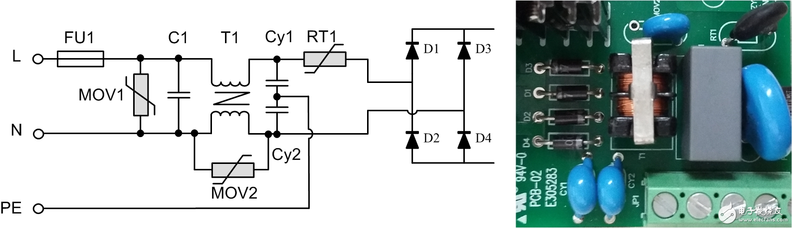
Figure 2 Example schematic and physical map
Differential mode surge test
When selecting the varistor, the maximum allowable voltage should be slightly greater than 350V. The maximum clamping voltage of this voltage varistor is about 1000V (at 50A test current). Secondly, in the differential mode path, equivalent to a voltage source with internal resistance of 2Ω and pulse voltage of 6KV in series with the varistor, the peak current is about (6KV-1KV)/2Ω=2500A. Finally, 681KD14 was chosen as the varistor. Its peak current is 4500A, the maximum allowable working voltage is 385VAC, and the maximum clamping voltage is 1120V.
Don't worry, because the uncoupled part of the common mode inductor, as a differential mode inductor in the differential mode path, will be divided into partial voltages. In fact, in the latter stage of the common mode inductor, the circuit has been protected and verified by experiments. Choose the commonly used 1N4007.
2. Common mode surge test
When the 6KV surge is tested on ACL-PE or ACN-PE, that is, the common mode surge test, the common mode path is equivalent to an internal resistance of about 12 Ω, and the voltage source with a pulse voltage of 6 kV is connected in series with the common mode inductor and the Y capacitor. Because the Y capacitor selects the Y1 class capacitor, its withstand voltage is high, and the energy of the 6KV common mode surge is not enough to make it damaged. Therefore, it is easy to pass the common mode surge by simply ensuring that the PE wiring and other wirings are kept indirect. test.
However, because of the high voltage across the common mode inductor during the surge test, arcing occurs. If it is close to the surrounding devices, it may damage the surrounding devices. Therefore, a discharge tube or a varistor can be connected in parallel to limit its voltage, thereby functioning as an arc extinguishing. As shown in MOV2 in the figure.
Another approach is to add a discharge tooth across the common-mode inductor during PCB design so that the inductor discharges through the two discharge tips, avoiding discharge through other paths, thereby minimizing the effects on surrounding and downstream devices. Figure 3 is a physical diagram of the discharge teeth added to the common mode inductor of the power supply module PCB of the model of PA1HBxOD-10W of Guangzhou Zhiyuan Electronics Co., Ltd.
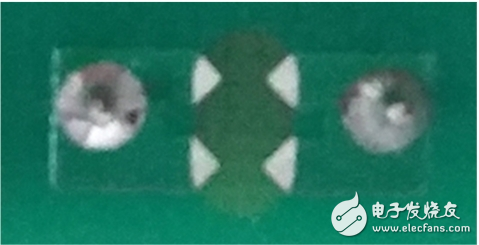
Figure 3 discharge tooth physical map
Fourth, summary
EMC testing is usually very practical, but if we master some basic principles, when designing the EMC pre-stage circuit, it will be more direction-tested, thus shortening the project development time. This article combines a simple example to introduce the pre-circuit device selection and typical circuit from the perspective of surge test. In the following articles, we will continue to explore the anti-surge circuit related content in more depth, and from other EMC Design the EMC pre-stage circuit from the perspective of performance indicators.
SPPA-R3000 Turbine Controls offers smooth and economic migration from an ISKAMATIC / SIMADYN / TELEPERM ME or a SIMADYN / S5/95 F environment. It is a perfect solution for gas and steam turbines of all producers, with electrical solutions, process engineering, comprehensive automation functions and a modern state of the art I&C system fully-integrated into the unit control.
Siemens Iskamatic Controller,Controller Plc Siemens,Siemens Cnc Control,Siemens Plc Controller
Xiamen The Anaswers Trade Co,.LTD , https://www.answersplc.com