The car alarm is a device installed on the car to increase the difficulty of car theft and extend the time of car theft. It is the protector of the car. By matching the anti-theft device with the car circuit, it can prevent theft, infringement and protection of the vehicle. With the development of computer networks and embedded technologies, car anti-theft systems have evolved from traditional mechanical and electronic anti-theft devices to more intelligent network-based anti-theft systems.
The IVI (In-Vehicle Infotainment) in-vehicle infotainment system is an in-vehicle integrated information processing system based on a vehicle-mounted bus system and an Internet service. IVI can realize a series of applications including 3D navigation, real-time road conditions, fault detection, vehicle information, mobile office, etc., greatly improving the electronic, network and intelligent level of vehicles.
The CAN (Controller Area Network) controller area network was developed by the German company BOSCH and eventually became an international standard. Among many automobile buses, CAN bus has an important position. It is a standard bus for communication between automotive electronic devices. It has been widely used in automotive distributed control systems. It has a CAN underlying protocol for large trucks and heavy machinery vehicles. The J1939 protocol. The system proposes a method for integrating the anti-theft function and the infotainment function of the automobile, and effectively utilizes the existing resources of the automobile to realize the optimization of the structure and function of the in-vehicle electronic system.
Compared with existing systems on the market, this system has the following advantages:
(1) Integrated design of anti-theft and infotainment system, low cost, simplified structure and powerful function;
(2) Adopting network-based anti-theft system, which has the advantages of stable operation, strong real-time performance and high reliability;
(3) The system CAN bus part can be combined with other body electronics systems to facilitate secondary development.
1 overall system design
1.1 Overall structure of the system
The system consists of a central control unit and a CAN network node. The central control unit selects the STM32F103X microprocessor produced by ST as the core, and combines GPRS wireless communication and other technologies to realize vehicle positioning, remote alarm and infotainment functions. The CAN network node includes the oil circuit node, the generator node and the DCM (Door Control Module) door control module node to realize vehicle condition monitoring and vehicle anti-theft function. The central control unit communicates with the CAN network node via the CAN bus. The overall structure of the system is shown in Figure 1.
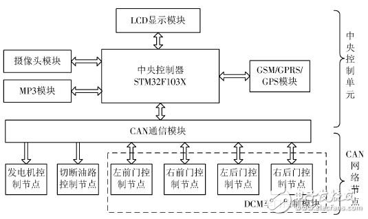
Figure 1 overall system block diagram
1.2 Implementation of anti-theft function
The anti-theft function of this system is designed to use the DCM and GPS positioning module as the monitoring nodes of the car safety status. When the system is set to the anti-theft mode, the DCM detects whether the car has been illegally invaded, and GPS positioning detects whether the car has been illegally moved. When detecting that the car is in an unsafe state, the GSM/GPRS communication module is first activated, and the GSM short message is used to transmit the locomotive position of the GPS location to the owner's mobile phone terminal through the GSM short message, so as to accurately locate the position of the car; After starting the car, the camera captures the image of the car, uses GPRS wireless communication technology to send the image to the owner's mobile phone terminal, assists the GPS to locate the car position; the central controller sends the signal to cut off the oil circuit and turn off the generator through the CAN bus, thereby effectively Avoid theft of cars.
1.3 Implementation of infotainment function
When the system is set to the normal mode, the LCD module displays the main menu interface, through the touch screen and buttons, for human-computer interaction and functional experience. The GSM/GPRS/GPS module is used to implement functions such as car phone and GPS positioning; the camera module is used to implement the car rear view function; the MP3 module is used to implement the voice playback function; and the LCD module is used for the interface display.
2 hardware design
The hardware design of the system mainly consists of two parts, one is the central control unit hardware design, and the other is the CAN network node hardware design. The system microcontroller is based on Cortex? The M3 core ARM microcontroller STM32F103X features low cost, low power consumption, and provides a viable design for systems that focus on power and efficiency.
2.1 Central Control Unit Hardware Design
The central control part mainly includes the microprocessor STM32F103ZET6, the MP3 module connected to the microcontroller through the SPI1 interface. The core of the module is the VS1053 produced by VLSI. It is a high performance, low power decoding chip; through the SPI2 interface and micro The LCD display module connected to the controller; the camera module connected to the microcontroller through the SCCB interface, the core of the module is the OV7670 produced by OV, which is small in size and low in operating voltage, and provides all functions of the single-chip VGA camera and image processor; The GSM/GPRS/GPS module connected to the microcontroller through the USART interface, the core of the module is SIM900A produced by SIM company, with stable performance, compact appearance and low power consumption; STM32 comes with bxCAN, which basically expands CAN, it supports 11 Bit's BasicCAN mode and 29-bit PeliCAN mode, communication rate up to 1 Mb/s, support time-triggered communication, 3 transmit mailboxes, 3 receive FIFOs with 3 levels of depth. The CAN transceiver uses NXP's TJA1050, which is fully compatible with the "ISO 11898" standard, high speed (up to 1 Mb/s), extremely low electromagnetic radiation, no power supply nodes will not interfere with the bus, and The differential receiver with wide common mode range has strong anti-electromagnetic interference capability and can connect at least 110 nodes, which is very suitable for this system. The hardware connection diagram of the central control part is shown in Figure 2.
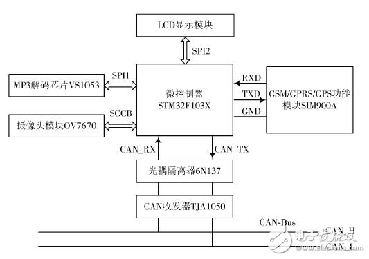
Figure 2 Central control part hardware connection diagram
2.2 CAN network node hardware design
The CAN network node mainly includes the microprocessor STM32F103C8T6, and its on-chip resources and related interfaces are sufficient to meet the functional requirements of this part, DCM nodes, oil circuit nodes, and generator nodes. DCM adopts UN4001 central control car lock, 12 V power supply, 360° rotor, super-power, anti-locking, etc. When the car is illegally opened, it sends an alarm signal to the central control unit via CAN bus; The oil circuit node receives the command through the CAN bus to operate. The design only needs to consider the CAN signal transmission problem. The hardware environment is simulated. The generator uses the No. 130 DC motor, and the motor is driven by the chip L298N. L298N is a kind produced by ST Company. High-voltage, high-current motor drive chip, control voltage DC is 5 V, motor voltage range is 3~46 V DC, with overvoltage and overcurrent protection, strong anti-interference ability; oil circuit node uses buzzer instead, The buzzer control circuit is composed of a triode, and the state of the buzzer is changed by the high and low levels of the PB0 output port, thereby simulating the switch of the oil passage. The hardware connection diagram of the CAN network node is shown in Figure 3.
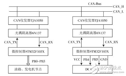
Figure 3 CAN network node hardware connection diagram
2.3 hardware physical map
According to the above introduction, the main hardware diagram completed is shown in Figure 4.
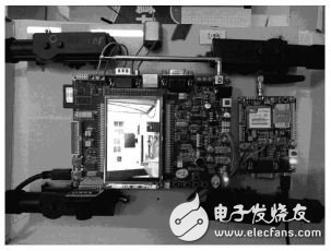
Figure 4 hardware physical map
3 system software design
The software design of the system mainly consists of two parts: the design of the anti-theft part and the design of the infotainment part.
3.1 system anti-theft function program design
The program flow chart of the anti-theft alarm part is shown in Figure 5.
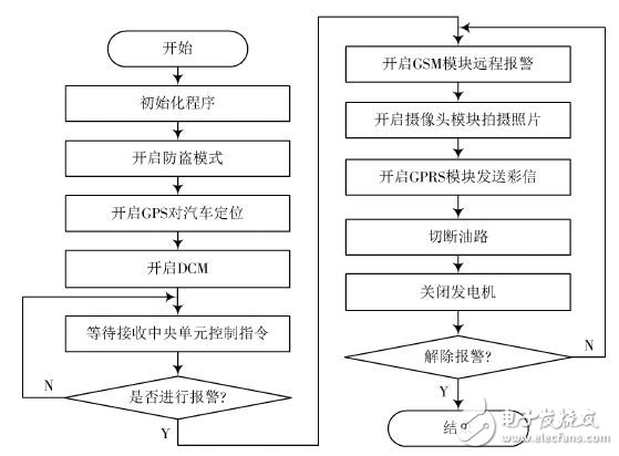
Figure 5 anti-theft function program flow chart
As shown in Figure 5, after the system is powered on, the program is initialized and the relevant registers and I/O ports are configured. The anti-theft mode is enabled, the GPS positioning and DCM start working, and the GPS positioning value is refreshed once for 30 s. When the current two positioning differences are greater than 50 m, the vehicle is stolen; in the anti-theft mode, the DCM detects that the door is opened and the vehicle is stolen. After determining that the vehicle has been stolen, the GSM communication function is activated, an alarm message is sent to the owner's mobile phone, and the position of the vehicle positioned by the GPS is periodically transmitted to the owner of the vehicle to monitor the position of the vehicle in real time. After the start, the CMOS camera on the door is photographed, the GPRS function is turned on, and the photographed photos are periodically sent to the owner's mobile phone through the GPRS network, and the assisted GPS tracks the car. Through the CAN bus, the controller sends a signal to cut off the oil circuit and turn off the generator to the vehicle oil circuit node and the generator node, so that the car can not run normally, thereby realizing the function of the car burglar alarm.
3.2 System information entertainment function program design
The program flow chart of the infotainment part is shown in Fig. 6.
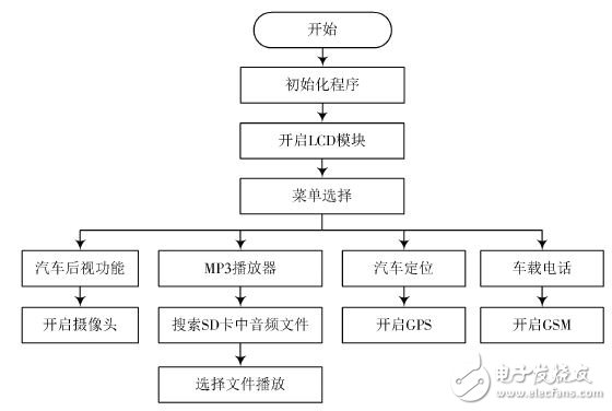
Figure 6 infotainment program flow chart
As shown in Figure 6, after the system is powered on, the subroutine is initialized first, and the relevant I/O ports and registers are configured. Then open the LCD module and enter the menu interface; click on the car rear view system, the camera module starts, display the image of the car on the LCD; click on the MP3 player, the system starts to search the voice play file in the SD card, select the file to play; click GPS positioning service, GPS positioning function is activated, the car position information is displayed on the LCD; click on the car phone, GSM communication function is activated, you can make a call and send a text message. Figure 7 is a human-computer interaction interface of an infotainment system.
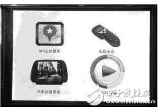
Figure 7 information entertainment system human-computer interaction interface
4 system test
4.1 Anti-theft function test and analysis
The system anti-theft function tests include CAN communication test and central unit test. The DCM, the oil circuit, and the generator node communicate with the main control unit through the CAN bus. The test steps are as follows:
(1) The central unit acts as a transmitting node, and the other nodes act as receiving nodes. Each node receives a control command issued by the central unit and gives a corresponding functional operation according to the command.
(2) The central unit acts as the receiving node, and the DCM acts as the transmitting node, sending feedback commands to the central unit, and the central unit gives corresponding functional operations according to the instructions. The central unit test mainly tests the GSM/GPRS alarm function. When the system detects that the car is stolen, it activates the GSM communication function, sends an alarm message to the owner's mobile phone, and periodically transmits the GPS position and latitude and longitude to the owner.
(3) Turn on the GPRS function, and periodically send the photos taken by the camera behind the car to the owner's mobile phone terminal through the GPRS network.
Figure 8 is a picture sent using the GPRS network, and Figure 9 is a GSM alarm message.
Figure 8 GPRS network information
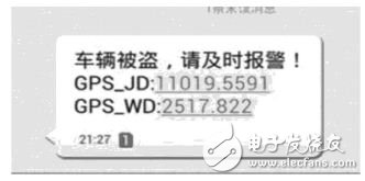
Figure 9 GSM short message
4.2 Information entertainment function testing and analysis
The system information entertainment function test mainly tests the four parts of the car phone, GPS positioning, rear view system and MP3 player. Considering that in some cases, the owner cannot communicate with the outside world through his own mobile device, the function of making a call and sending a text message through the car phone can be used as the backup phone of the owner. GPS positioning can accurately display the latitude and longitude of the car, combined with Google Maps can achieve car navigation. The rear view system is tested at a speed of 10 km/h, and the shooting picture is clear and real-time. The MP3 player's volume output has a high amplitude, full sound, and easy operation. Figure 10 is an operation interface of a car phone.
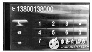
Figure 10 car phone
5 Conclusion
This paper proposes a method of integrating car anti-theft function and infotainment function, and based on CAN communication and GPRS communication technology, effectively utilizes the existing resources of the car, and designs and implements a set of car anti-theft and infotainment functions. The intelligent system completes the optimization of the structure and function of the in-vehicle electronic system. Through the design of the system software and hardware and the actual test of the system, the system infotainment part runs stably and is easy to operate, and the anti-theft part has the advantages of high speed, real-time and reliability. The CAN bus part of the system can communicate with other electronic systems of the vehicle body, which has far-reaching significance for the development of the vehicle electronic system.
Drum Sieve,Thailand Paddy Cleaner,Paddy Drum Pre Cleaner,Grain Drum Pre-Cleaner
WOSENS TECHNOLOGY Co., LTD , https://www.wosenstechnology.com