GPS (Global Positioning System) is a next-generation satellite navigation and positioning system developed by the U.S. Department of Defense in 1973, with development spanning over two decades. As a global, all-weather, continuous, and real-time positioning system, GPS offers omnidirectional, real-time, three-dimensional navigation and positioning capabilities for land, sea, and air. It provides users with accurate, real-time, and continuous 3D position, speed, and time references.
Currently, China is working on the construction of the BeiDou Navigation Satellite System, planning to launch five geostationary orbit satellites and 30 non-geostationary orbit satellites to create a global BeiDou satellite navigation system. According to the development plan, around 2012, the BeiDou system was expected to provide navigation, timing, and short message communication services across the Asia-Pacific region. By 2020, a fully global BeiDou navigation system was set to be completed.
For many years, China relied heavily on importing GPS receivers from abroad. Most of these receivers used foreign GPS-specific chips, which were not only costly but also limited by foreign technology, making them unsuitable for military or high-demand applications. Therefore, developing GPS digital receivers with independent intellectual property is of great strategic importance. Independent development can overcome foreign technological restrictions and improve performance in high-dynamic and real-time environments. It also paves the way for the development of BeiDou-based navigation receivers, supporting the growth of the "Beidou" system and accumulating valuable technical experience. This article focuses on the design of a GPS front-end system using the GP2010 as its core component.
**1. Mobile GPS Front-End Overall Design**
The design centers around Zarlink's dedicated chip, the GP2010. The antenna receives the L1 band signal from GPS satellites, which is then filtered through a passive bandpass filter and amplified by a low-noise amplifier before entering the GP2010 chip. After three stages of down-conversion, the RF signal is adjusted via amplification and filtering, converted into an intermediate frequency (IF) signal, and finally digitized by a two-bit analog-to-digital converter for further baseband processing.
**1.1 RF Signal Processing Module: GP2010**
GP2010 is a low-power, low-cost, and highly reliable GPS RF front-end chip from Zarlink Semiconductor. It comes in a TQFP44 package and operates between 3V and 5V, consuming only 200 mW at 3V. The chip processes the satellite’s L1 band navigation signal, which is input through a passive filter, low-noise amplifier, and impedance-matched microstrip line. It performs the down-conversion process, converting the RF signal into a digital intermediate frequency signal.
The GP2010 includes an on-chip frequency synthesizer, divider, mixer, automatic gain controller (AGC), and quantizer that provides digital symbol and magnitude outputs. With this chip, only minimal peripheral circuits are needed to build a complete GPS receiver front-end. It can be paired with Zarlink’s 12-channel digital correlator GP2021 or GP4020 baseband processor to form a full GPS receiver platform. Although the chip handles most of the key functions, some components like the reference clock crystal oscillator circuit, first-stage IF filter, and second-stage IF filter must be designed externally. The third-stage IF filter is integrated on-chip, with an output center frequency of 4.309 MHz.
**1.2 First-Stage IF Filter Circuit Design**
During the three-stage down-conversion process, the local oscillator mixes with the satellite signal, generating both upper and lower sidebands. A three-stage bandpass filter selects the lower sideband while suppressing the upper sideband and any leakage. This multi-level filtering enhances the receiver’s resistance to interference.
The first stage of GP2010 converts the 1,575.42 MHz satellite signal to 175.42 MHz. The first-stage IF filter is placed between the first and second stages of frequency conversion, effectively filtering out image interference and RF leakage. While RF filters can also handle such issues, Zarlink recommends using the first-stage IF filter for optimal performance. The first-stage mixing requires a DC offset to maximize the IF signal processing range. Typically, the first-stage IF filter includes a DC path implemented via a pull-up inductor. Additionally, AC coupling between stages is used, and the design incorporates two adjustable IC filters with resonators for AC decoupling. The schematic of the first-stage IF filter is shown in Figure 1.
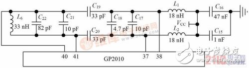
*Figure 1: Schematic of the first-stage IF filter circuit*
**1.3 Second-Stage IF Filter Design**
The second-stage filter is connected between the output of the second mixer and the input of the third mixer. It filters the second-stage IF signal to reduce interference before it reaches the third mixer. Based on the characteristics of the second-stage mixing output, the filter should have a center frequency of 35.42 MHz and a bandwidth of ±1 MHz. According to Zarlink’s specifications, the filter insertion loss should be between 1.4 and 1.8 dB, with a 2 MHz bandwidth and at least 20 dB of attenuation for out-of-band signals. The schematic of the second-stage IF filter is shown in Figure 2.
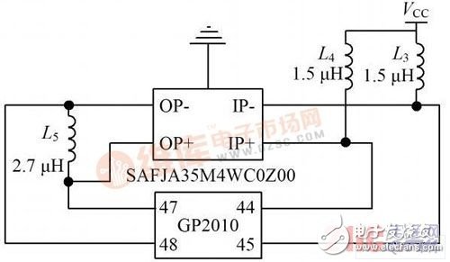
*Figure 2: Schematic of the second-stage IF filter circuit*
**2. GPS RF Front-End Actual Circuit Board**
The actual circuit board of the GPS RF front-end is built based on the above design principles, ensuring stable and accurate signal processing. It integrates all necessary components, including the GP2010 chip, IF filters, and other supporting circuits. The layout is optimized for performance, minimizing noise and interference. This board serves as a foundation for further development of advanced GPS and BeiDou navigation systems.
Double Concave Lens
Bi-Concave (Double-Concave) lenses have equal radius of curvature on both sides of the lens and function similarly to plano-concave lenses by causing collimated incident light to diverge.
Double-Concave Lenses are used in beam expansion, image reduction, or light projection applications. These lenses are also ideal for expanding the focal length of an optical system. Double-Concave Lenses, which have two concave surfaces, are Optical Lenses with negative focal lengths.
Realpoo Optics offers double concave lens, and they are available in several anti-reflection coating optics, including MgF2, VIS 0°, VIS-NIR, NIR I, or NIR II, for optimal performance in the Ultraviolet (UV), Visible, or Infrared (IR) regions.
Lens Optical,Optical Coating,Double Concave Lens,Optics Image
Changchun Realpoo Photoelectric Co., Ltd. , https://www.optics-realpoo.com