1 Introduction This article takes a mixed flow unit as an example, the unit is equipped with a T-100 type governor, and briefly describes the process of using PLC to realize the automatic control of the turbine unit. In China, the comprehensive automation of small hydropower is gaining more and more attention, because the traditional backward control method makes every small hydropower have to rely on duty personnel to operate on site, not only wasting human and material resources, but also not conducive to the large-scale development of small hydropower. This control device is specially designed for automatic control of small and medium-sized hydro-generator sets. This system fully takes into account the characteristics of the operation of small hydropower stations in China at present, and replaces the original relay contactor control system.
2 Equipment process characteristics and control requirements
2.1 Automatic control engineering content of the power station
(1) After the command pulse is issued, the unit's start-up, grid connection, load regulation, shutdown, power generation to phase-modulated operation and phase-modulated forwarding electrical operation, etc., all need to be completed automatically;
(2) It can automatically maintain the normal working conditions of the unit, such as speed adjustment and excitation adjustment, bearing lubrication and cooling, phase-modulated pressurized water, etc .;
(3) The automatic operation of the front gate of the turbine and the auxiliary equipment and public equipment of the unit;
(4) When the unit has an accident, it will automatically shut down and remove the unit from the system; when the unit has an abnormal state, it will automatically send an alarm signal and take predetermined measures to resume normal work.
2.2 Unit control process The automatic control of the unit includes automatic control of the unit's lubrication system, cooling system, braking system and phase-regulated water pressure system, the unit's start and stop, the unit is transferred from the phase modulation to the power, and from the power generation to the conversion of the equivalent working conditions , Unit protection and signal, etc.
The following gives the block diagram of the unit start, stop, and power generation phase modulation operation procedures, as shown in Figures 1, 2, and 3.
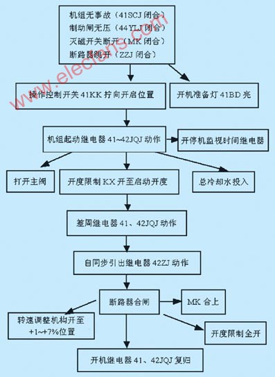
Figure 1 Block diagram of unit start-up operation

Figure 2 Flow chart of the normal shutdown operation of the unit

Fig.3 Flow chart of the operation procedure of generating unit transfer from power generation to phase modulation 3.1 Hardware design
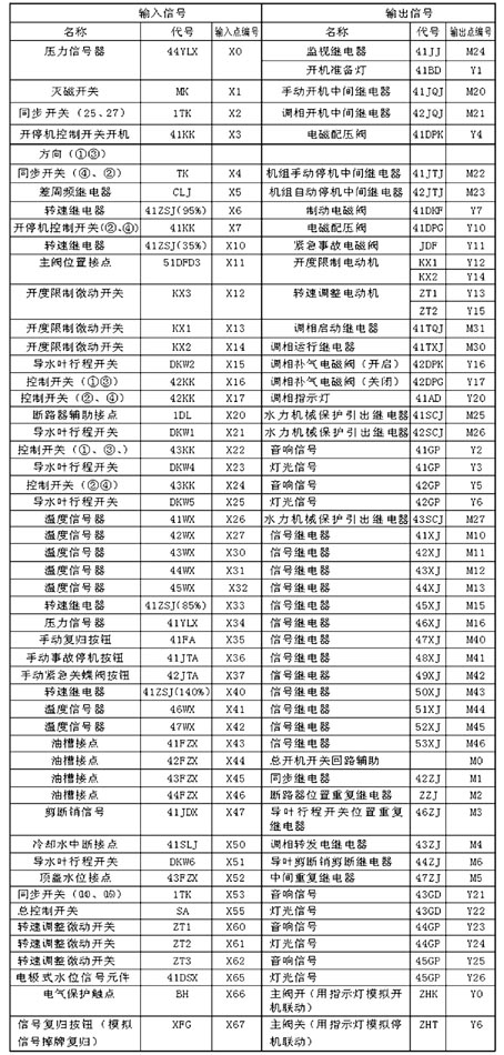
(1) The assignment of input and output points and the arrangement of auxiliary relay M are shown in the attached table.
Schedule input and output point allocation and main auxiliary relay M arrangement table
According to the use points of I / O and considering the future development needs, it is decided to adopt Mitsubishi FX2N-128MR PLC.
(2) PLC wiring diagram For PLC wiring, see Figure 4. The input point of the PLC is always a normally open contact, and the load is uniformly 110V DC power supply. The phase-modulated water level signal device 41DSX and the guide vane shear pin signal device 41JDX need to be connected to another 220V AC power supply (this part of the circuit is omitted), and connect its contact to the PLC input point. The comparison circuit of the frequency difference relay CLJ is cancelled, and its contacts are replaced with switch simulations.
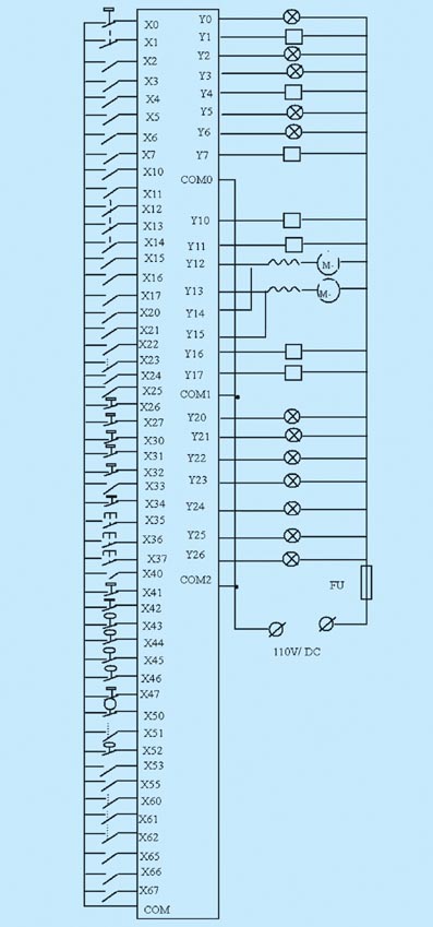
Figure 4 PLC wiring diagram
3.2 Programming The ladder diagram program is shown in Figure 5.
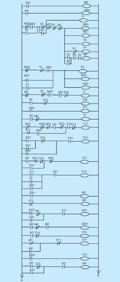
Figure 5 Ladder diagram (a)

Figure 5 Ladder diagram (b)

Figure 5 Ladder diagram (c)
4 Conclusion
Since the PLC is used to simulate the automatic control system of the small hydropower station, its performance is much superior to the original relay contactor control. At the same time, due to convenient operation, safety and reliability, intuitive display of various signals, the failure rate is greatly reduced, and almost zero failure of the control system is realized. The device has a good market.
Our T-Bulb Light is made of pure PC material with two connectors B22&E27. T-bulbs use non-isolated driver and the voltage is 170-300V. The T-shaped shell and turnable axis are the unique features of T-bulbs. It has 10 watt power and its CRI is more 80, luminous efficiency is 80LM/W. The color temperatures include cool white, warm white and natural white. This type of bulbs light is in elegant shape, easy installation and good quality. These T-bulb lamps have a two-year warranty, mainly used in office, bedroom, supermarket and so on.
Type T Bulb Led,T Led Bulb Price,T Bulb,Type T Light Bulb Led
Jiangmen Lika Lighting Electrical Appliances Co., Ltd , https://www.lika-led.com